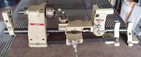
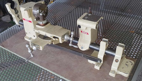
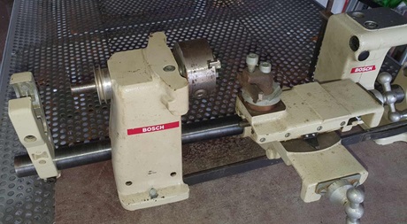
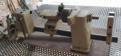
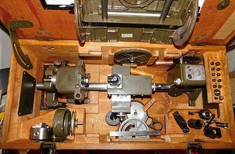
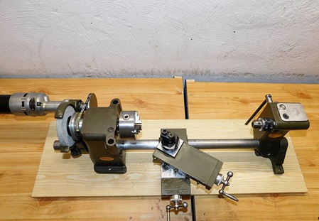
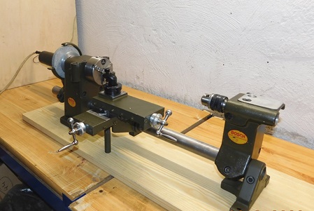
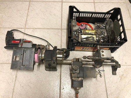
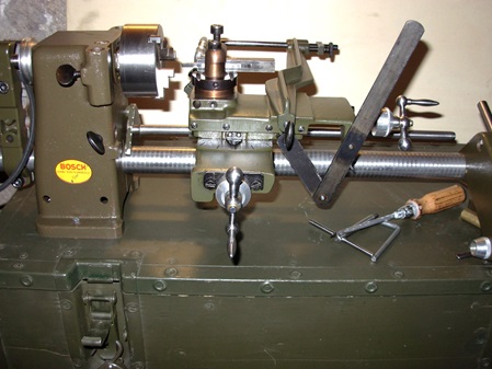
Die Drehmaschine.
The lathe.
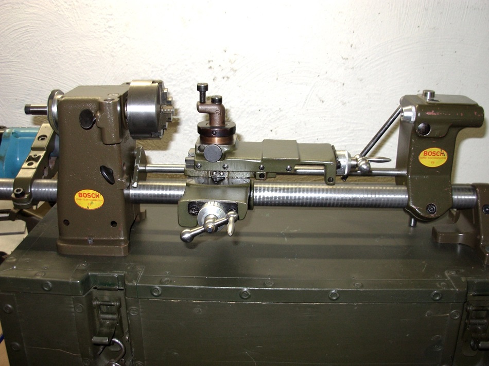
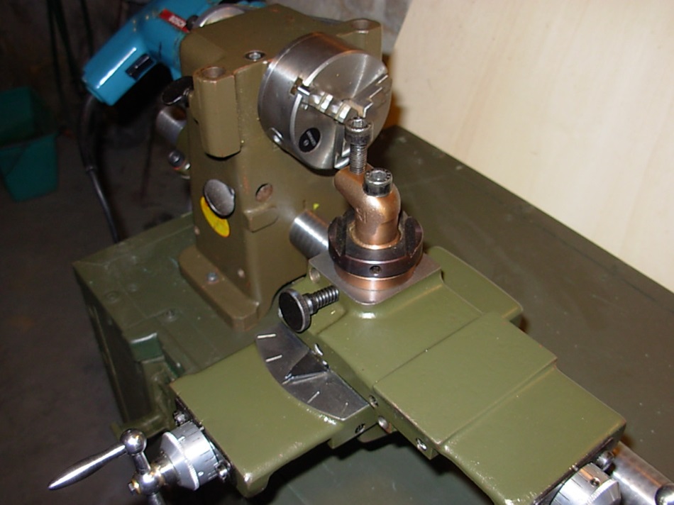
Bosch Combi Drehmaschine.
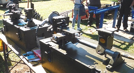
Es ist die höchste Ausbaustufe vom Bosch-Combi und entspricht der 2. und 3. Ausführungs-Variante ab Ende der 50ziger Jahre.
Die letzte Ausführung der Drehmaschine war allerdings ohne die Aufnahmebohrungen für die Zusatzgeräte. Das war eine reine Drehmaschine. Man konnte allerdings den großen Sägetisch und den Tischhalter mit den dazu gehörenden Zusatzgeräten (Wanknut-Säge) weiter nutzen.
Die Drehmaschine war schon vor vielen Jahren "der Traum" während meiner Berufsausbildung.
Nach langer Suche und vielen Fehlschlägen konnte ich meine erste Bosch-Combi-Drehmaschine in den 90ziger Jahren bei einer Internet- Auktion- Plattform für eine akzeptable Summe ersteigern.
Mittlerweile besitze ich zwei dieser Maschinen. Die Zweite war leider nicht vollständig und musste von mir ergänzt werden.
Dazu finden sie in der Rubrik "Ersatzteile" einen Beitrag.
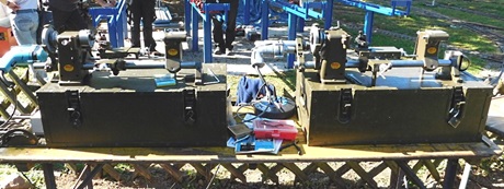
Meine beiden, hier gezeigten Maschine, sind aus dem Jahre 1963.
Ich habe im Laufe der Zeit auch schon Ausstattungen aus dem Jahre 1960 gesehen. Da waren allerdings nur die älteren Komponenten verstaut. Der große Sägetisch war da noch nicht dabei.
Aus meiner aktiven Militärzeit Ende der 70ziger Jahre war mir bekannt, dass auch bei der Bundeswehr das Bosch Combi System im Einsatz war. Allerdings fand ich es nur im stationären Hausmeister-Bereich der Kompanie-Gebäude.
Dass dieses Gerät in einer Vollausstattung der Truppe in Tarnfarbe zur Verfügung stand, war mir bis Dato völlig unbekannt.
Das System besteht, sowohl aus Komponenten der Anfangszeit (Bandsäge) den Teilen der späten 50ziger Jahre, als auch den neuen Komponenten aus den 60ziger Jahren.
Bandsäge, Bandschleifer und Dekupiersäge, sowie der kleine Sägetisch und die Abrichthobelwalze sind noch aus den 50ziger Jahren. Zur Benutzung ist unbedingt der Spindelstock mit den dafür vorgesehenen Befestigungs-Bohrungen erforderlich.
Die letzte Serie des Spindelstockes, vor der Einstellung der Produktion, hatte diese Bohrungen nicht mehr. Die Bohrungen waren in der Ausführung von 1968 schon nicht mehr vorhanden. Die Kopiereinrichtung und alle Zusatzgeräte, die auf den Spindelstock aufbauten, konnte damit nicht mehr verwendet werden.
Die neuen Ausrüstungsmerkmale, wie der große Sägetisch mit Wanknuteinrichtung und der dazu gehörende Tischhalter sind aus den 60ziger Jahren.
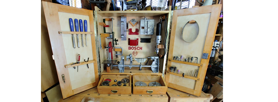
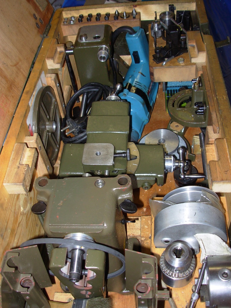
In zwei Koffern ist alles für kleine Metall- und Holzarbeiten untergebracht. Die Zubehörteile für den Spindelstock (Band- und Dekupiersäge sowie der Bandschleifer) sind sehr selten zu finden.
Die Verantwortlichen des Bundeswehr-Beschaffungsamtes haben dabei ganze Arbeit geleistet. Sie haben alle brauchbaren Teile der letzten 10 Jahre zusammengestellt und in zwei Kisten verpackt.
Ob damit jemals ein Soldat gearbeitet hat, ist eine ganz andere Geschichte.
Ich habe die Info bekommen, dass diese Maschine den Waffentechnikern zur Verfügung gestellt wurde um kleinere Reparaturen vor zu nehmen.
Ich benutze diese Maschinen nicht im täglichen Gebrauch, dafür ist der Montage-Aufwand zu hoch. Sie stehen immer in ihrer Kiste gut verstaut in meiner Werkstatt.
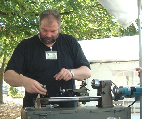
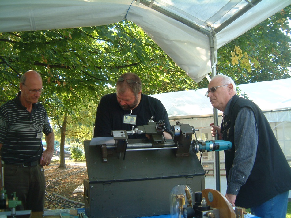
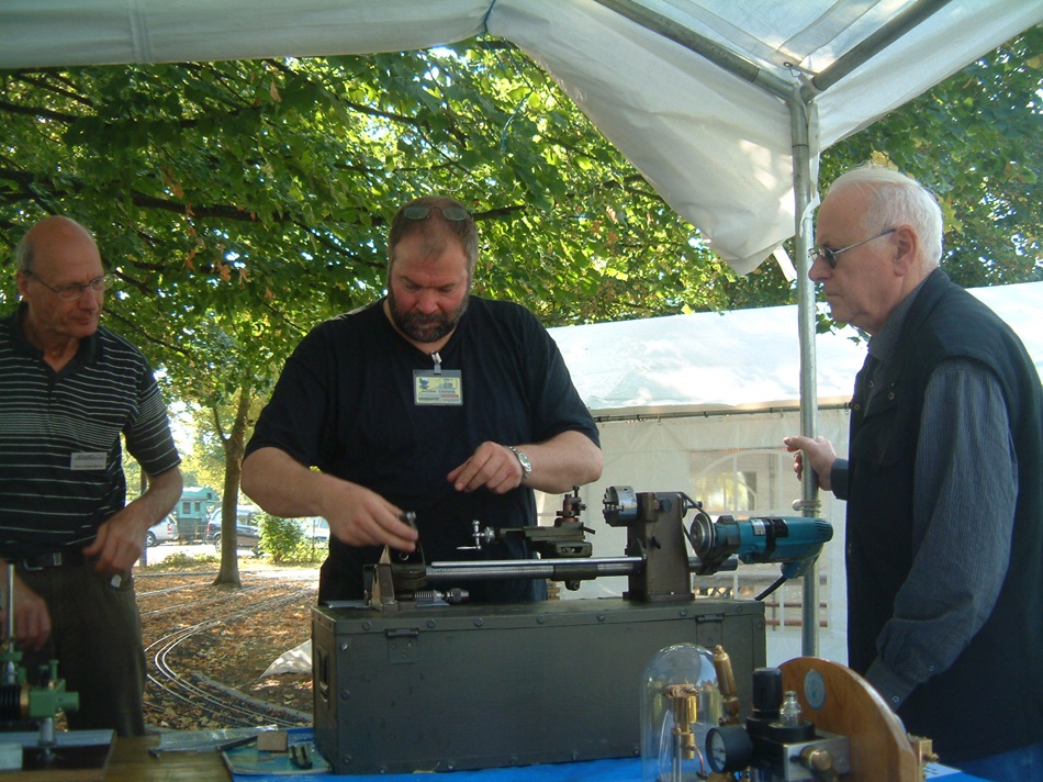
Bei Ausstellungen führe ich diese Maschine gelegentlich gerne vor.
Eine Beschreibung dieser Maschine finden sie auch auf einer englischen Webseite.
http://www.lathes.co.uk/bosch/
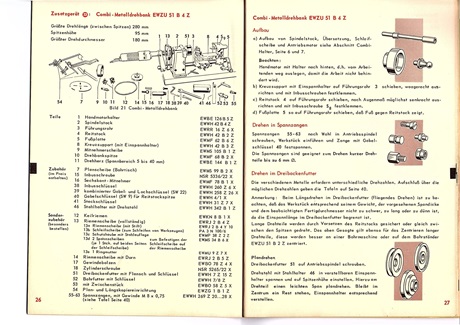
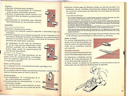
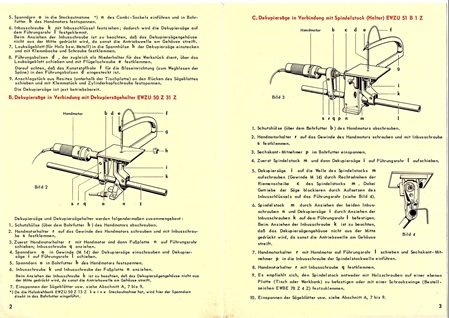
Auszug aus der Bedienungsanleitung für die Drehmaschine. -->> Klick
Hier ist der grundsätzliche Aufbau des Spindelstockes mit dem Tischträger zu sehen. -->> Klick
Hier ein kleines Video von einer Drehmaschine mit originalem Antrieb. -->> Klick
Hier ein weiteres kleines Video einer handelsüblichen Maschine. -->> Klick
Bosch Combi lathe.
It is the highest configuration level of the Bosch Combi and corresponds to the 2nd and 3rd version from the end of the 1950s.
However, the last version of the lathe was without the mounting holes for the additional devices. This was a pure lathe. However, it was still possible to use the large saw table and the table holder with the associated attachments (wall groove saw).
The lathe had been my "dream" during my vocational training many years ago.
After a long search and many failures, I was able to buy my first Bosch Combi lathe at an internet auction platform in the 1990s for a reasonable sum.
I now own two of these machines. Unfortunately, the second one was not complete and I had to replace it.
You can find an article on this in the "Spare parts" section.
My two machines shown here are from 1963.
In the course of time, I have also seen equipment from 1960. However, only the older components were stowed there. The large saw table was not yet there.
From my active military days at the end of the 1970s, I knew that the Bosch Combi System was also used by the German army. However, I only found it in the stationary facility management area of the company buildings.
The fact that this device was available to the troops in full camouflage was completely unknown to me until then.
The system consists of components from the early days (band saw), the parts from the late 50s, as well as the new components from the 60s.
Band saw, belt sander and scroll saw, as well as the small saw table and the jointer roll are still from the 50s. The headstock with the holes provided for it is essential for use.
The last series of the headstock, before production stopped, no longer had these bores. The bores were already no longer present in the 1968 version. The copying device and all additional devices that were based on the headstock could therefore no longer be used.
The new equipment, such as the large saw table with roll grooving device and the table holder belonging to it are from the 60s.
Two cases hold everything for small metal and wood work. The headstock accessories (band saw, scroll saw and the belt sander) are very rare to find.
The officials of the Bundeswehr acquisition office have done a great job. They have collected all usable parts of the last 10 years and packed them into two boxes.
Whether a soldier has ever worked with them is another story.
I got the info that this machine was made available to the weapons technicians to make minor repairs.
I don't use these machines on a daily basis, the assembly effort is too high for that. They are always well stored in their box in my workshop.
I like to demonstrate these machines occasionally at exhibitions.
Techn. Daten der Maschine.
Spitzenhöhe: 95mm
Durchmesser Max.: 190mm
Spitzenweite: ca. 320mm mit langem Rohr: ca. 850mm.
Drehfutter Durchmesser: 74mm mit Umkehrbacken.
Technical data of the machine.
Centre height: 95mm
Max. diameter: 190mm
Centre distance: approx. 320mm with long tube: approx. 850mm.
Lathe chuck diameter: 74mm with reversible jaws.
Beschreibung
Auszug aus einer Beschreibung aus dem Jahre 1957.
Die komplette Bedienungsanleitung finden sie auf der entsprechenden Seite dieser Homepage.
Extract from a description from 1957.
The complete operating instructions can be found on the corresponding page of this homepage.
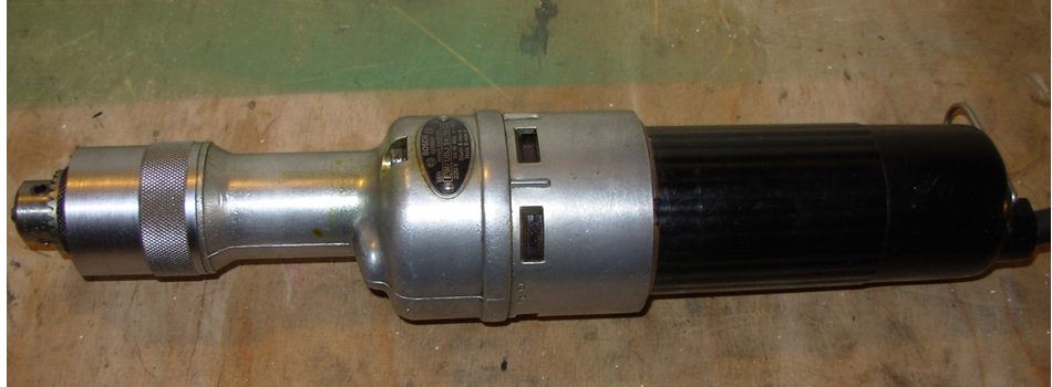
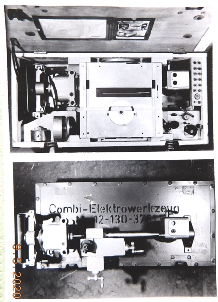
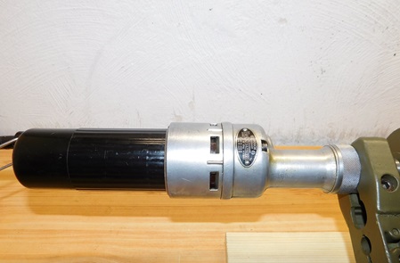
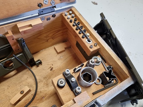
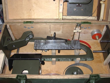 In der Kiste 1 von 2 sind die Zusatzgeräte, die auf dem Spindelstock basierten untergebracht. Als Anriebsmaschine war der Bosch-Handmotor EW/UBJ 54/19 mit 140 Watt Aufnahmeleistung und 50 Watt Abgabeleistung vorgesehen, der entweder direkt über einen Sechskant-Mitnehmer oder über das Riemenvorgelege gekoppelt wurde.
Box 1 of 2 housed the additional equipment that was based on the headstock. The driving machine was the Bosch EW/UBJ 54/19 hand motor with 140 watts input power and 50 watts output power, which was coupled either directly via a hexagonal driver or via the belt transmission.
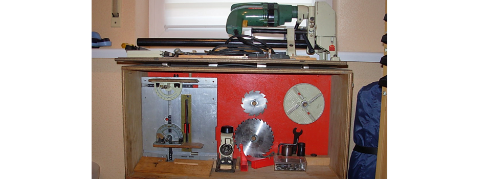
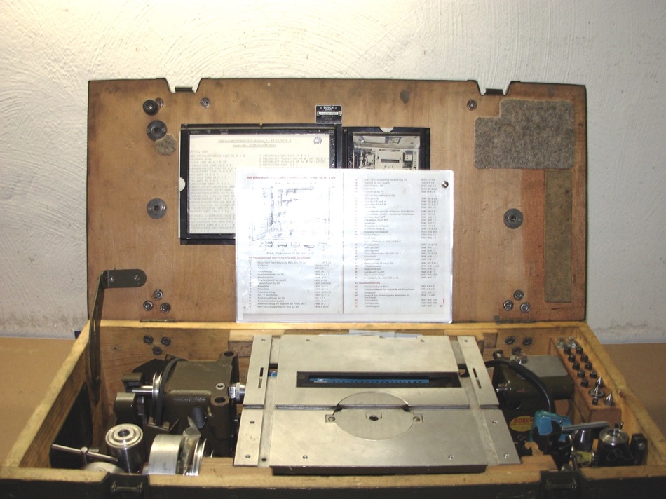
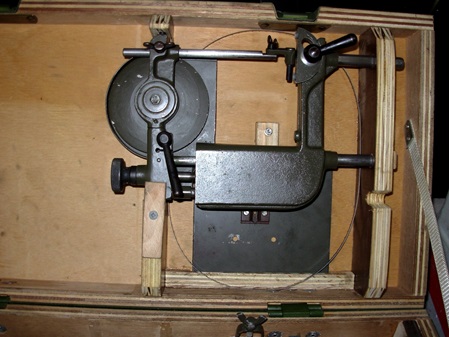
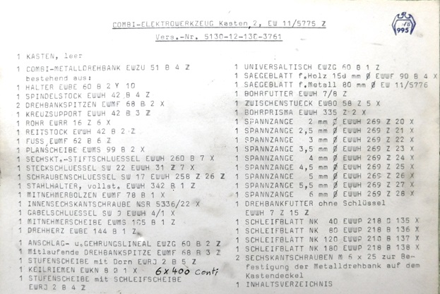
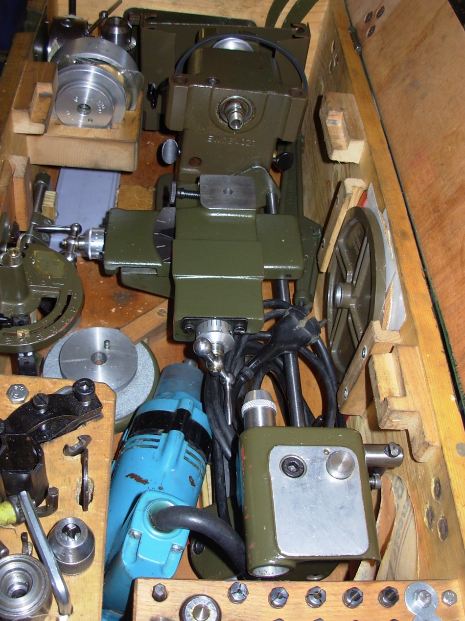
In box 2 of 2 is the lathe with all accessories from the 60s.
Summary of box 2 These two documents are placed in the lid below.
Drehmaschine aus der letzten Fertigungsreihe.
Ein freundlicher User hat mir einige Bilder einer Maschine der letzten Fertigungsreihe zukommen lassen, die ich ihnen nicht vorenthalten möchte.
Lathe from the last production series.
A friendly user sent me some pictures of a machine from the last production series, which I would like to share with you.
The last version before production was ended.
It's amazing that the toggle cranks didn't break.
Man findet selten heute noch komplette Maschinen.
Irgend ein Teil geht da immer im Laufe der Zeit verloren oder geht kaputt.
It is rare to find complete machines today.
Some part always gets lost or broken in the course of time.
Hier kommen ein paar kurze Videos, die ich von meinen Maschinen gefertigt habe.
Here are a few short videos that I have made of my machines.
Weitere Videos finden sie auf meinem Kanal bei YouTube.
You can find more videos on my channel on YouTube.
Meine zweite Bosch Combi Drehmaschine aus dem Jahre 1963 mit dem, von mir, nachgebauten Kreuzsupport und ergänzten Kurbeln.
My second Bosch Combi lathe from 1963 with the cross support I rebuilt and added cranks.
Contents of box 2, here with reconstructed cross support. The original cross support was missing from this machine.
Die Fa. Proxxon bietet ein Dreibackenfutter für ihre Drehmaschine PD 250e unter der Nr. 24034 mit 75 mm Durchmesser an. Dieses Futter passt ausgezeichnet zur Bosch-Combi Drehmaschine. Es wird lediglich ein Zwischenflansch, ähnlich dem zum Sanou-Futter benötigt.
Proxxon offers a three-jaw chuck for its PD 250e lathe under no. 24034 with a diameter of 75 mm. This chuck is an excellent fit for the Bosch Combi lathe. Only an intermediate flange, similar to the Sanou chuck, is required.
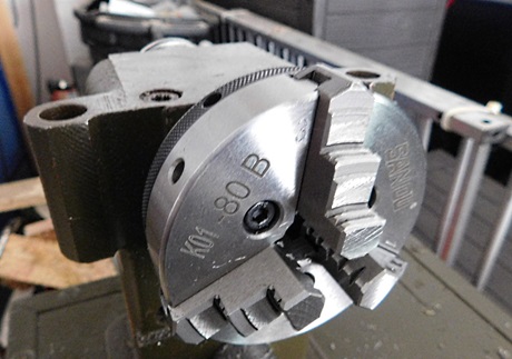 Bei einigen, auf dem Gebrauchtmarkt erhältlichen Maschinen, fehlt leider immer einmal wieder das Drehfutter. Dieses ist nicht mehr erhältlich. Ein gutes passendes Futter stellt die Fa. "SANOU" her. Allerdings benötigt man für die Montage einen Adapterflansch. Diesen Flansch habe ich mir passend hergestellt.
Mehr dazu findet man auf der Seite "Ersatzteile".
With some machines available on the second-hand market, the lathe chuck is sometimes missing. This is no longer for sale. A good suitable chuck is manufactured by the company "SANOU". However, you need an adapter flange for the assembly. I have made this flange to fit.
More can be found on the page "Spare parts".
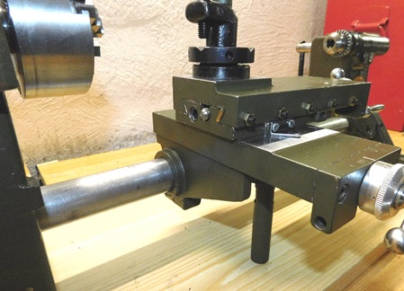 Mehr zur Nachfertigung vom Kreuzschlitten finden sie in der Rubrik "Ersatzteile"
You can find more information about the reproduction of the cross slides in the category "spare parts".
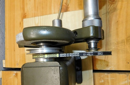
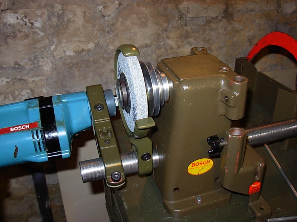
With the grinding wheel assembly, two additional speeds are available, so that a total of 6 speeds can be realized.
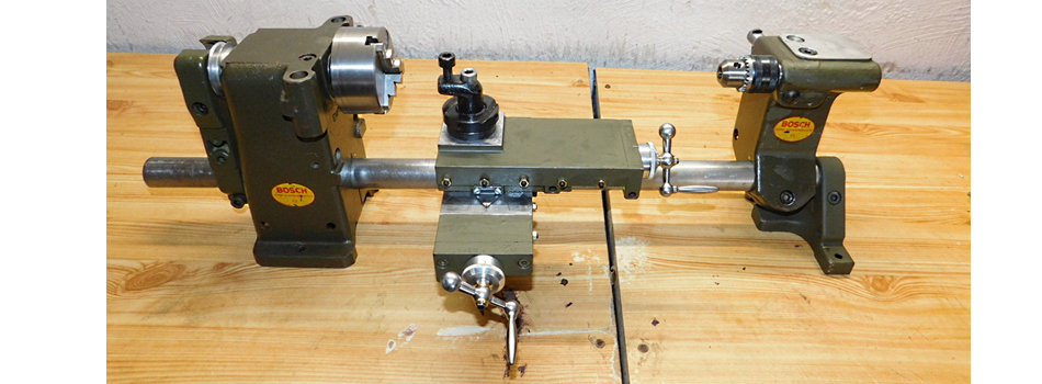
Bosch Combi Drehmaschine aus dem Jahre 1968/69, die bisher letzte Ausführung, die ich gesehen habe, die an die Bundeswehr ausgeliefert wurde.
Bosch Combi lathe from 1968/69, so far the last version I have seen that was delivered to the German armed forces.
16.12.2022
Ich habe bei E-Bay eine Anzeige für eine Drehmaschine gefunden. Nach Rückfrage bei dem Anbieter habe ich die Genehmigung zur Veröffentlichung der Bilder erhalten. An dieser Stelle vielen Dank an Christian Sohr.
Die Maschine wurde inzwischen versteigert. Ich wünsche dem neuen Eigner viel Spaß damit.
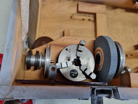
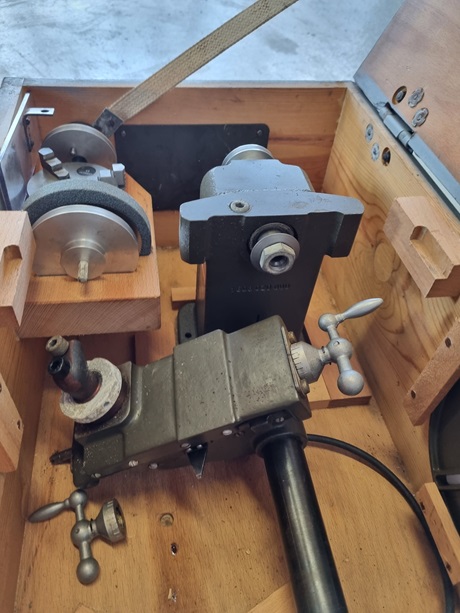
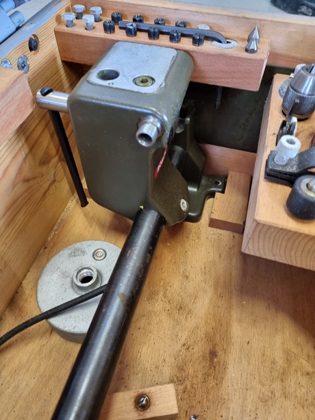
Die Maschine stellt die letzte Version der Drehmaschine dar. Die Bohrungen im Spindelstock für die unterschiedlichen Zusatzgeräte sind hier nicht mehr vorhanden. Es ist also nicht mehr möglich, den Band-Schleifer oder die Bandsäge zu montieren. Der Durchbruch für die Hobelwalze im Sägetisch ist allerdings noch vorhanden.
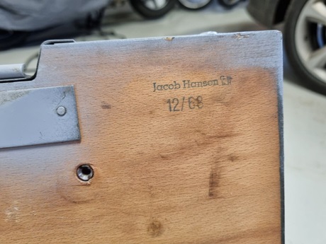
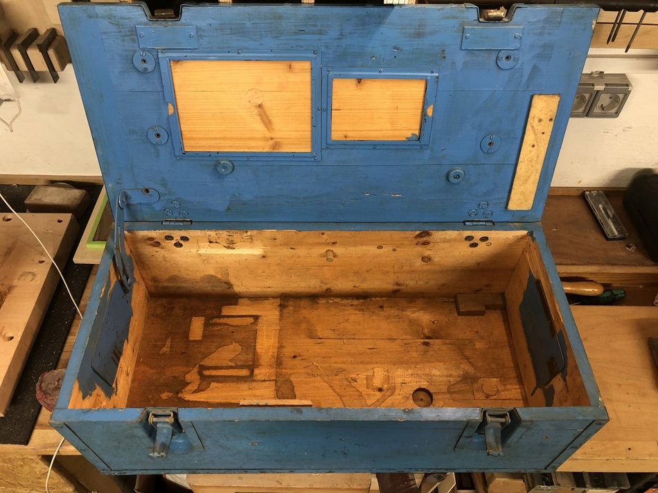
Lt. Stempelung im Deckel der Aufbewahrungskiste wurde diese im Jahre 1968 gefertigt. Der Stempel kennzeichnet wahrscheinlich den Hersteller der Aufbewahrungskiste. Die Maschine selbst kann auch schon vor 1968 gefertigt worden sein oder auch nach 12/1968.
So genau ist das leider anhand der Bilder nicht zu datieren.
Bemerkenswert ist, dass bei dieser Maschine die Kurbeln nicht zerbrochen sind und anscheinend die Kiste vollständig ist.
I found an advertisement for a lathe on E-Bay. After contacting the seller, I received permission to publish the pictures. Many thanks to Christian Sohr at this point.
In the meantime, the machine was auctioned. I wish the new owner a lot of fun with it.
The machine is the latest version of the lathe. The holes in the headstock for the various attachments are no longer present here. So it is no longer possible to mount the belt grinder or the band saw. However, the breakthrough for the planing roller in the saw table is still there.
According to the stamp in the lid of the storage box, it was manufactured in 1968. The stamp probably identifies the manufacturer of the storage box. The machine itself could also have been manufactured before 1968 or even after 12/1968.
Unfortunately, it is not possible to date it that precisely from the pictures.
Remarkably, the cranks on this machine are not broken and apparently the box is complete.
The box has a slightly more modern design and has been repainted once.
Here you can clearly see that the various mounting holes for the old accessories are missing. The holes for the hand levers, for copying, are also no longer present on the support.
The other equipment is the same as in 1963.
Bosch Combi Drehmaschine für die Bundeswehr aus dem Jahre 1960 mit Originalausstattung der damaligen Zeit .
Ich habe freundlicherweise einige Bilder von einem User zur Verfügung gestellt bekommen, die eine frühe Ausführung der Maschine für die Bundeswehr zeigen. Baujahr der Maschine ist 1960, also 3 Jahre früher als meine beiden Maschinen.
Auffällig ist, dass 1960 der kleine Sägetisch zur Ausstattung gehörte. Offenbar wurde zwischen 1960 und 1963 die Ausstattung für die Bundeswehr geändert. Die Unterbringung der Teile ist unterschiedlich gelöst worden. Die allgemeinen Ausstattungsteile, bis auf den großen Sägetisch, Tischhalter und Anschlaglineal sind jedoch identisch.
Der Zustand der Maschine ist als ausgesprochen "desolat" zu bezeichnen. Sie stand wohl lange Zeit ungenutzt auf einem Speicher oder in irgend einer Scheune. Anscheinend wurde die Kiste einmal aufgebrochen. Das würde die fehlenden Verschluss-Haken am Deckel der Kiste erklären.
Bevor man mit so einer Maschine wieder arbeiten kann, muss man viel Zeit, Geduld und Geld investieren.
I have kindly been provided with some pictures by a user showing an early version of the machine for the Bundeswehr. The machine was built in 1960, 3 years earlier than my two machines.
It is noticeable that in 1960 the small saw table was part of the equipment. Obviously, the equipment for the Bundeswehr was changed between 1960 and 1963. The accommodation of the parts was solved differently. However, the general equipment parts, except for the large saw table, table holder and fence ruler are identical.
The condition of the machine can be described as "desolate". It probably stood unused for a long time in an attic or in some barn. Apparently the box was once broken into. This would explain the missing locking hooks on the lid of the box.
Before you can work with such a machine again, you have to invest a lot of time, patience and money.
18.03.2022
Ein weiterer User hat mir Bilder einer Maschine zukommen lassen, die er evtl. verkaufen möchte.
Die Maschine wurde ebenfalls um ca. 1957- 1960 gebaut.
A user has sent me pictures of a machine that he might want to sell.
The machine was also built around 1957 - 1960.
Die Maschine wurde sehr wahrscheinlich ebenfalls an die Streitkräfte geliefert.
Eine entsprechende Holzkiste war dabei.
Allerdings wurden wohl die Aufbewahrungs- und Arretierungsklötze aus der Kiste entfernt.
The machine was most likely also delivered to the armed forces.
A corresponding wooden box was included.
However, the storage and locking blocks were probably removed from the box.
Aber Achtung !!
Eine ähnliche Maschine, die allerdings total verbastelt war, habe ich letztens auf einem Flohmarkt entdeckt. Der Verkäufer hatte wahnwitzige Preisvorstellungen. Als er mir seine Preisvorstellung nannte, hab ich ihn ausgelacht, habe mich umgedreht und bin gegangen.
Er wird wohl noch einen Dummen finden, der ihm das Teil für zu viel Geld abkauft.
Liebe Leser, lasst Euch nicht von so dubiosen Händlern, ob nun auf dem Flohmarkt oder im Internet, über's Ohr hauen.
Warning!!!
I recently discovered a similar machine at a second-hand flea market, but it was completely tinkered with. The seller had insane price expectations. When he told me his asking price, I laughed at him, turned around and left.
He will probably find a stupid person who will buy the part from him for the money demanded.
Dear readers, don't let yourself be ripped off by such dubious dealers, whether at second-hand markets or on the internet.
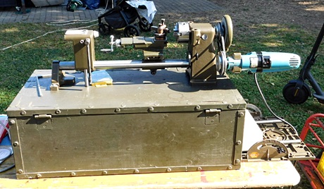
Bosch Combi Drehmaschine aus dem Jahre 1963 mit neu gefertigten Kurbeln.
Das ist meine erste Maschine, die ich nach langem Suchen vor etlichen Jahren erstehen konnte.
Bosch Combi lathe from 1963 with newly manufactured cranks.
This is my first machine, which I was able to purchase after a long search several years ago.
Die Bosch Combi Drehmaschine.
Als ich diese, meine erste Maschine bekam, war noch das Korresionsschutzfett von der Einlagerung der Maschine vorhanden.
Augenscheinlich wurde diese Maschine zuvor noch nie benutzt. Nur das Drehfutter hatte einige Flugrost-Spuren durch Handschweiß vom Auspacken.
Die originalen Handkurbeln, mit feststehender Skalierung, waren aus einer sehr schlechten, porösen Aluminium Gusslegierung und mutmaßlich beim Auspacken der Maschine zerbrochen.
Die neuen Handkurbeln habe ich aus Stahl gefertigt und mit verstellbaren Skalenringen versehen.
Die Maschine wird auf dem Deckel der Kiste 2 befestigt. Dazu sind von der Innenseite des Deckels Einschlagmuttern verbaut.
$$$$$$$$$$$$$$$$$$$$$$$$$$$$
Leider findet man immer mal wieder Angebote, bei denen der Kreuzsupport fehlt. Diese Teile sind eigentlich nur als Teileträger für die Ersatzteil-Beschaffung zu gebrauchen.
Die dafür aufgerufenen Preise sind manchmal überhöhte Wunschvorstellungen der Anbieter und entbehren jeglicher Grundlage.
Aber wie lautet der Spruch: "jeden Tag steht einer auf, der ……….."
Bei diesen Bieter-Schlachten mach ich nicht mit.
$$$$$$$$$$$$$$$$$$$$$$$$$$$$
Ich habe vor nicht all zu langer Zeit, eine solche Bundeswehrmaschine "ohne" den Kreuzsupport für wenige Euros angeboten bekommen und auch erworben.
Der Anbieter war nicht all zu weit weg von mir, so konnte ich die Maschine persönlich begutachten und mit nehmen.
Den fehlenden Kreuzsupport habe ich nachgefertigt. Dazu ist in der Rubrik "Ersatzteile" ein Bericht eingestellt.
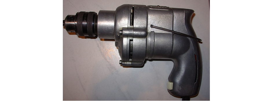
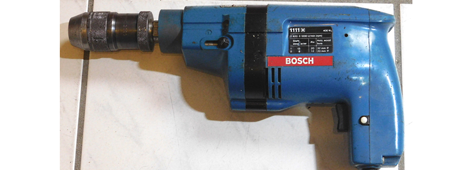
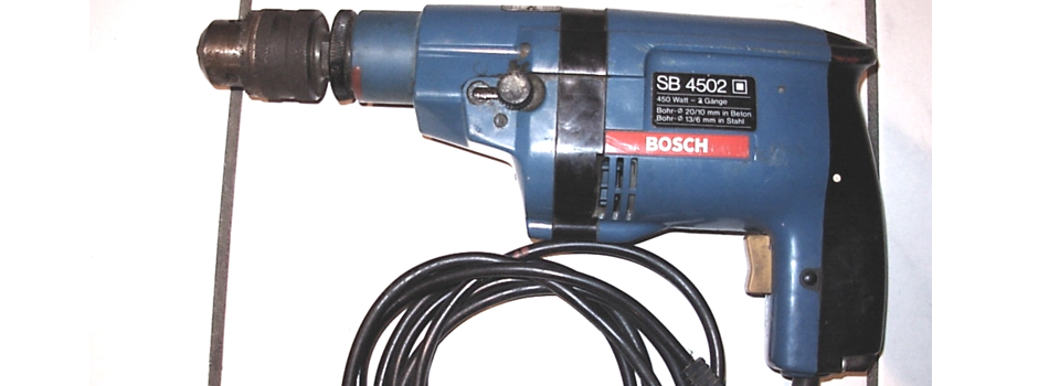
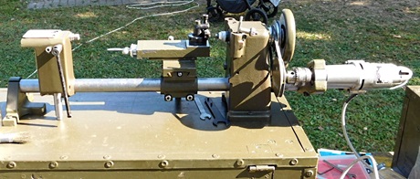
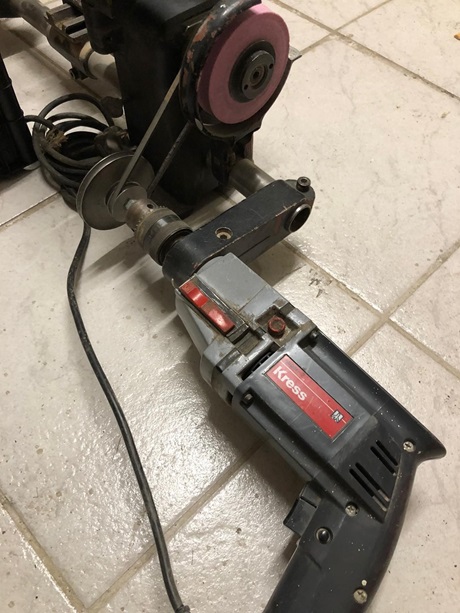
Als Antrieb verwende ich bei dieser Drehmaschine eine Bosch-Bohrmaschine "M41 S". Die Maschine hat kein Schlagwerk.
Es handelt sich um eine 4 Gang Bohrmaschine mit 2 mechanischen Gänge und 2 elektrischen Gänge.Die elektrischen Gänge werden durch einen Schalter und eine Leistungsdiode realisiert. Dadurch läuft der Motor nur mit einer Halbwelle und die Drehzahl sowie die Leistung reduzierten sich um ca. die Hälfte.Maximal-Leistung: 400 Watt.
Es ist aber auch jede andere Bohrmaschine mit einem Ø43mm Spannhals und einer Bohrfutteraufnahme mit dem Gewinde 1/2" x 20 Gang UNF verwendbar.
Wenn man alle Teile zusammen nimmt, kommt man gut und gerne auf einen damaligen Beschaffungspreis, für den man schon einen Kleinwagen bekam, nur für die Teile im Koffer 2. allerdings ohne die Antriebsmaschine.
Jeder kann sich selbst ausrechnen, was die Teile heute kosten würden, wenn sie denn noch hergestellt würden.
Da sind Maschinen aus dem Land von Konfuzius wesentlich günstiger zu bekommen. Ob diese allerdings nach 60 Jahren auch noch so aussehen und auch noch funktionieren, da mag sich jeder seine eigene Meinung bilden.
Diese Bosch Drehmaschine ist deutsche Wertarbeit.
Das Gesamtgewicht der Kiste 2 mit allem Inhalt liegt bei ca. 45 - 50 Kg.
The Bosch Combi lathe.
The machine still had the anti-corrosion grease from the storage.
Apparently this machine had never been used before. Only the lathe chuck had some traces of flash rust from hand sweat from unpacking.
The original hand cranks were made of a very bad cast aluminium alloy and apparently broke when unpacking the machine.
I made the new cranks from steel and added adjustable scale rings.
The machine is fixed on the lid of box 2. For this purpose, drive-in nuts are installed from the inside of the lid.
Unfortunately, one finds from time to time offers, where the cross slides is missing. These parts are actually only to be used as part carriers for spare parts procurement.
The prices called up for this are sometimes exaggerated wishful thinking of the offerers and are without any basis.
I do not take part in these bidding battles.
Not too long ago, I was offered such a Bundeswehr machine "without" the cross slides for a few euros and also bought it. The missing cross slides I have reproduced. There is a report about it in the category "spare parts".
For this lathe I use a Bosch drill "M41 S" as drive. The machine has no percussion mechanism.
It is a 4-speed drill with 2 mechanical gears and 2 electric gears.
The electrical gears are realized by a switch and a power diode. This means that the motor runs with only one half-shaft and the speed as well as the power are reduced by about half.
Maximum power: 400 watts.
Any other drill with a Ø 43 mm chuck neck and a UNF 1/2" x 20 threaded drill chuck can also be used.
If you take all parts together, you can easily get a purchase price at that time, for which you already got a small car, only for the parts in case 2. but without the engine.
Everyone can calculate for himself how much the parts would cost today.
Machines from the land of the rising sun are much cheaper. But whether they still look like this after 60 years, everyone may form their own opinion.
This Bosch lathe is high quality German made.
The total weight of case 2 with all contents is about 45Kg.
Hier habe ich ein kleines Video gedreht um die Möglichkeiten der Drehmaschine zu zeigen.
Here I made a little video to show the possibilities of the lathe.
Bosch Combi Drehmaschine
Weitere Videos finden sie auf meinem Kanal bei YouTube.
You can find more videos on my channel on YouTube.
Das Gerät besteht aus einem Materialmix.
Der Spindelstock und der Kreuzsupport bestehen augenscheinlich aus weißem Temperguss. Für Grauguss ist das Material zu hart und für Stahlguss sind die Wandstärken zu gering. Solche filigranen Teile hat man gerne aus weißem Temperguss hergestellt.
Die Spindel besteht aus Stahl und läuft an der Futterseite in einem normalen Kugellager und an der Riemenscheibe in einem Schulterlager, ähnlich wie die Lagerung einer Fahrradkurbel. Die Lager sind durch ein Federelement vorgespannt.
Der Reitstock und der Bohrmaschinen-Halter sind aus Aluminium-Druckguss gefertigt.
Alles wird durch ein Ø 30 mm Stahlrohr zusammen gehalten.
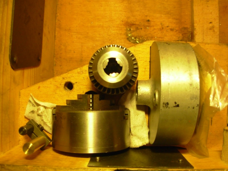
Das Ø 74 mm Dreibacken-Drehfutter mit Wendebacken wurde von der Fa. Röhm hergestellt und mit dem Bosch-Logo versehen. Es wird direkt, ohne Zwischenflansch, auf die Drehspindel geschraubt. Die Spindelaufnahme ist in Anlehnung an DIN 800 gestaltet. Das Aufnahmegewinde ist M 14 x 1,5 mm. Der Zentrierbund hat Ø 16 mm.
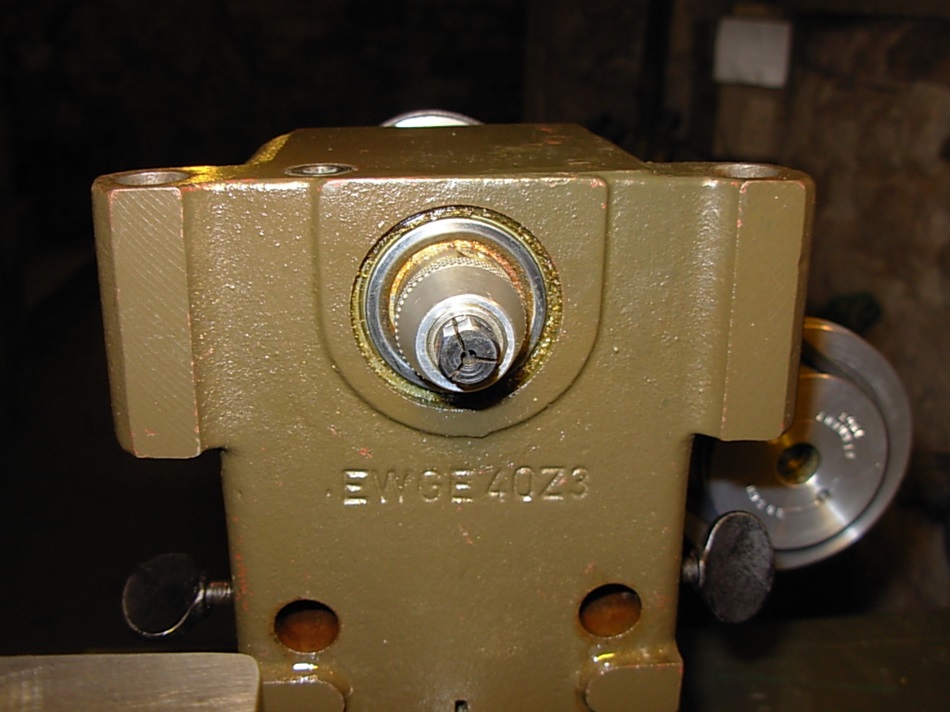
Die Drehspindel und auch die Reitstockpinole haben identische Aufnahmen auch für den Einsatz von Spannzangen ist ein Gewinde von M 8 x 0,75 in der Dreh- und Reitstock-Spindel eingearbeitet.
The device consists of a material mix.
The headstock and the cross slides are apparently made of white tempered cast iron. The material is too hard for grey cast iron and the wall thicknesses are too thin for cast steel. Such filigree parts are often made of white tempered cast iron.
The spindle is made of steel and runs in a normal ball bearing on the chuck side and in a angular ball bearing on the pulley. The bearings are preloaded by a spring element.
The tailstock and the driving machine holder are made of aluminium die-cast.
Everything is held together by a Ø 30mm steel tube.
The 74 mm diameter three-jaw lathe chuck with reversible jaws was manufactured by Röhm and marked with the Bosch logo. It is screwed directly onto the turning spindle. The spindle holder is designed according to DIN 800. The mounting thread is M14 x 1.5mm. The centering collar has a diameter of 16mm.
The turning spindle and also the tailstock quill have identical receptacles also for the use of collets.
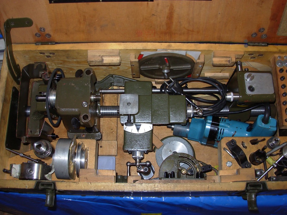 Alles hat seinen Platz und ist für den Transport gut geschützt. Ursprünglich war da ein Handmotor von Bosch dabei mit 140 Watt Aufnahme-Leistung, der in der Kiste 1 seinen Platz hatte.
Da ich auf Ausstellungen eigentlich nur die Kiste 2 zum Vorführen mit nehme, habe ich die Bohrmaschine in dieser Kiste verstaut.
Everything has its place and is well protected for transport. Originally there was a hand motor from Bosch with 140 watts input power, which had its place in box 1.
On exhibitions I only take box 2 with me for demonstrations, so I put the drilling machine in this box.
The second, slightly smaller shaft behind the guide tube is the holder for the copying unit.
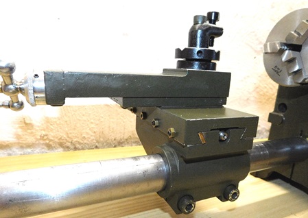
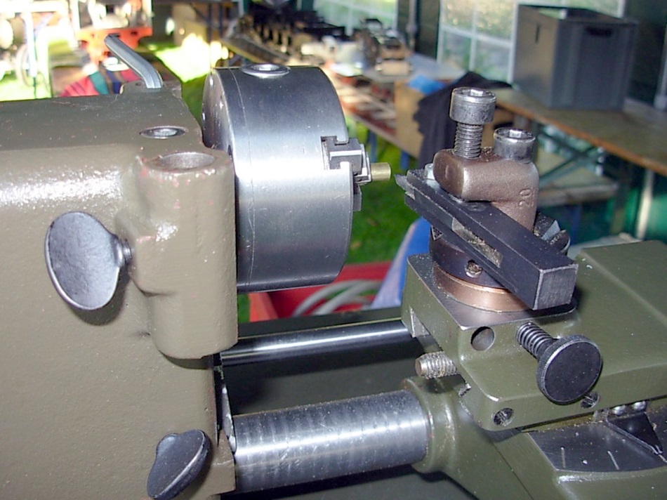
A simple screwing device makes it easy to adjust the height of the turning tool.
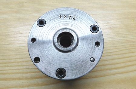
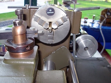 Das 74mm Drehfutter ist von der Fa.Röhm und wurde mit dem Bosch-Logo ausgeliefert.
Das Futter wird direkt, ohne Zwischenflansch, auf die Drehspindel aufgeschraubt.
Aufnahmegewinde ist M14 x 1,5mm .
Für einen Freund, der auch eine Bosch-Combi Drehmaschine hat, habe ich einen Flansch für ein 80mm Drehfutter angefertigt.
Mehr dazu finden sie unter Ersatzteile.
Lathe chuck backside.
The 74mm lathe chuck is from the Röhm company and was delivered with the Bosch logo.
The chuck is screwed directly onto the turning spindle without any flange.
The mounting thread is M14 x 1,5mm .
For a friend, who also has a Bosch-Combi lathe, I made a flange for an 80mm lathe chuck.
You can find more information under spare parts.
The additional grinding wheel also provides two additional drive stages.
Thus, a total of 6 different speed stages are available in addition to the 4 gears of the drill.
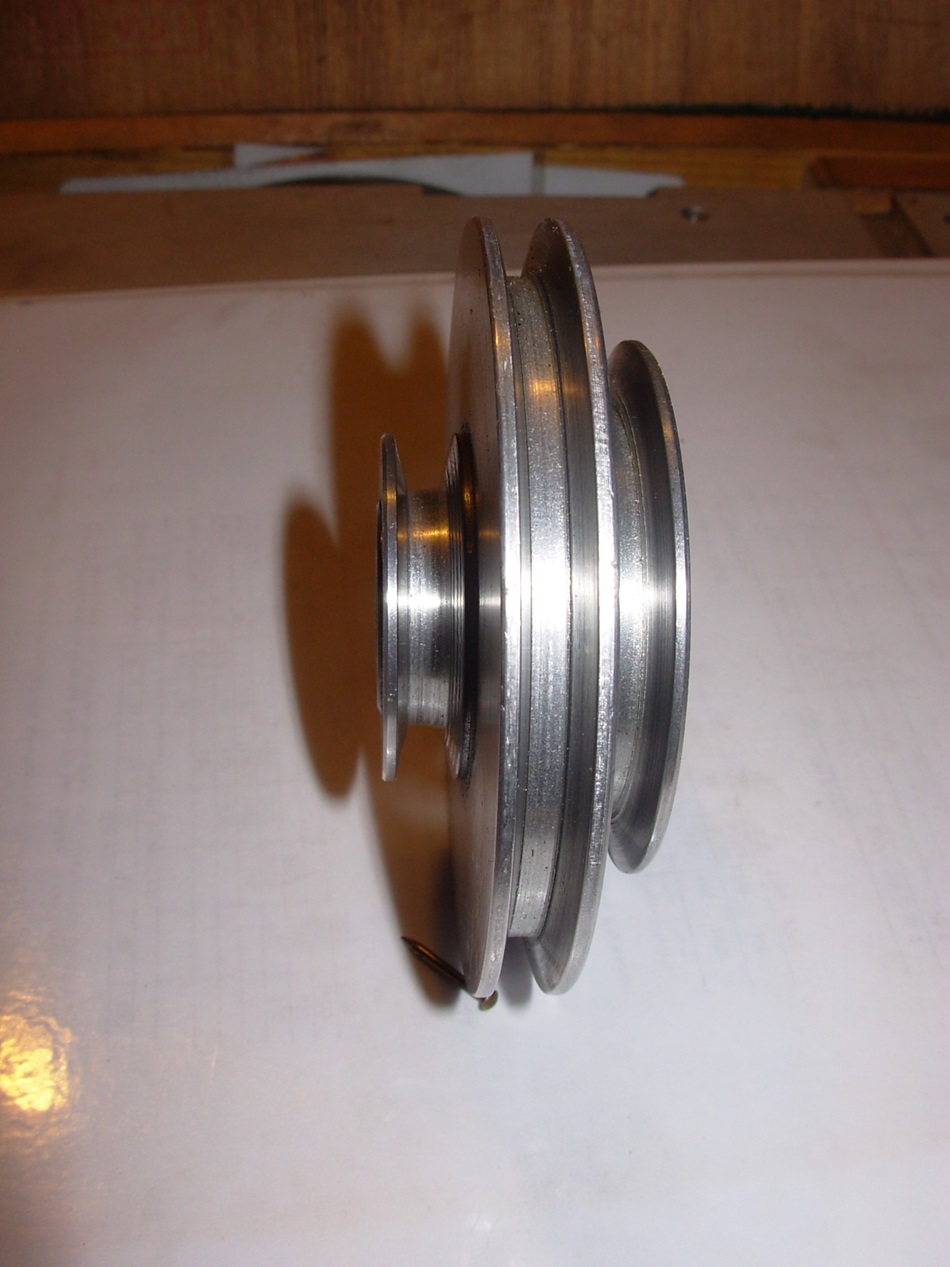
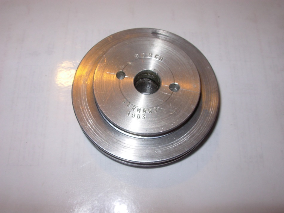
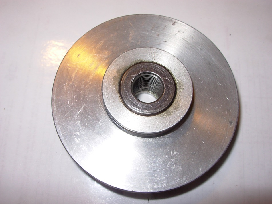
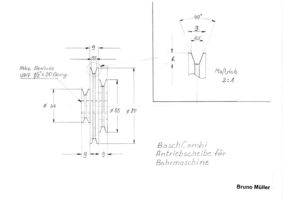
This is the drive pulley for the belt drive, it is screwed directly onto the drill spindle. The original part had a 6mm hexagonal clamping shaft for the hand motor.
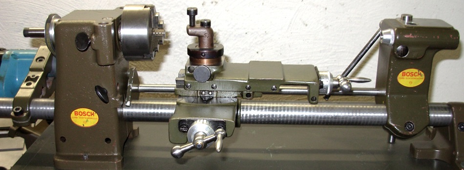
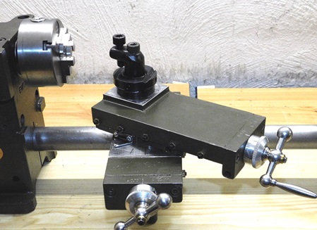
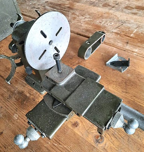
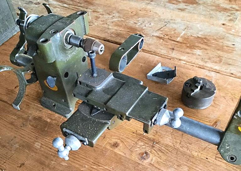
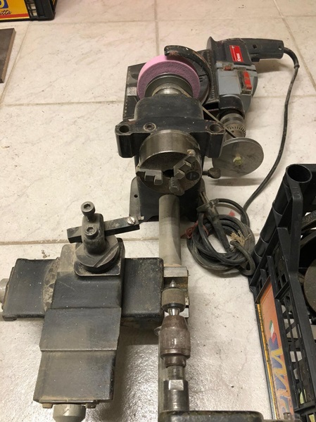
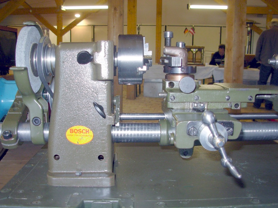
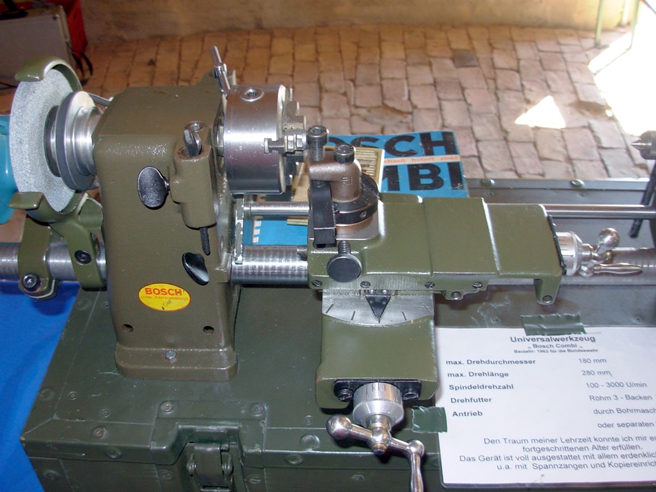
Headstock with lathe chuck and cross slides.
The two holes for the Bosch wrench are located on a bolt circle of 28mm. The holes have a diameter of 4.5mm.
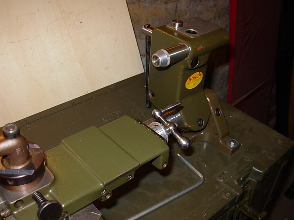
Tailstock. The aluminium nut on the tailstock spindle sleeve is only to protect the thread.
In the hub is a thread for the drill spindle. Here I mounted a clamping nut for the Bosch Combi with socket glue. You can also cut a thread UNF 1/2" x 20 gear directly.
Here I have made a small drawing of the drive pulley. The dimensions are in millimeters. I have deliberately omitted tolerance specifications.
Please click on the picture to enlarge it.
Die Zusatzgeräte.
Diese sind teilweise nur mit dem Spindelstock verwendbar.
Die Dekupiersäge kann auch mit einem Zusatzhalter und einem kurzen Rohrstück unabhängig vom Spindelstock genutzt werden.
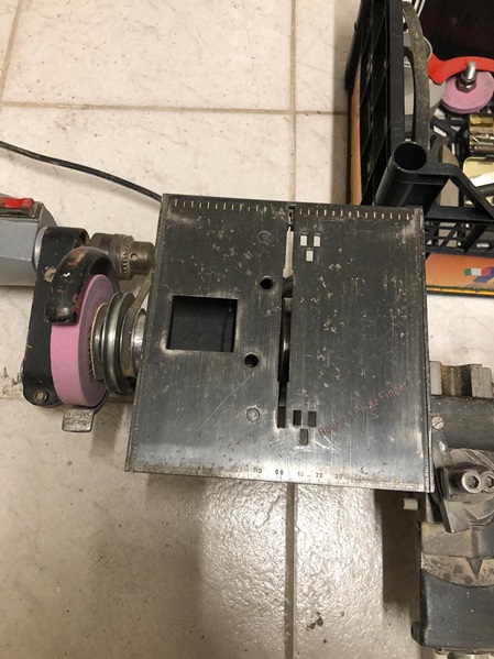
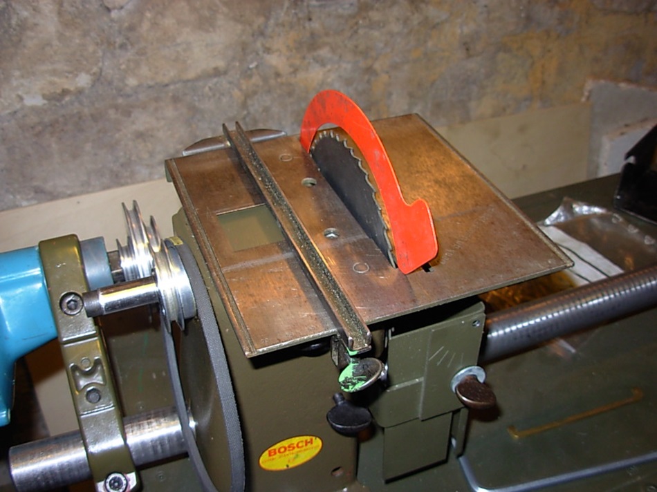
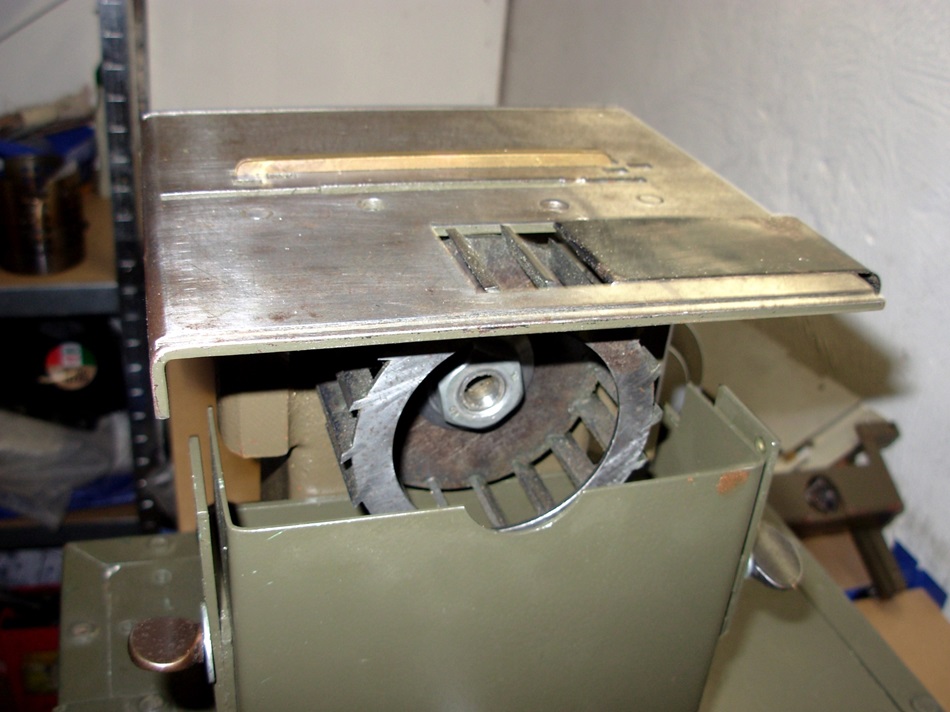
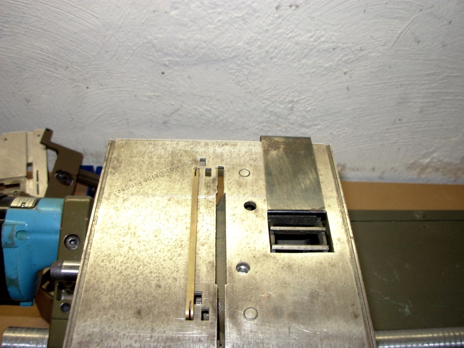
Belt transmission and small saw table for saw blades up to max. 125 mm. The table does not swivel, but its height can be adjusted.
It can only be used in combination with the headstock.
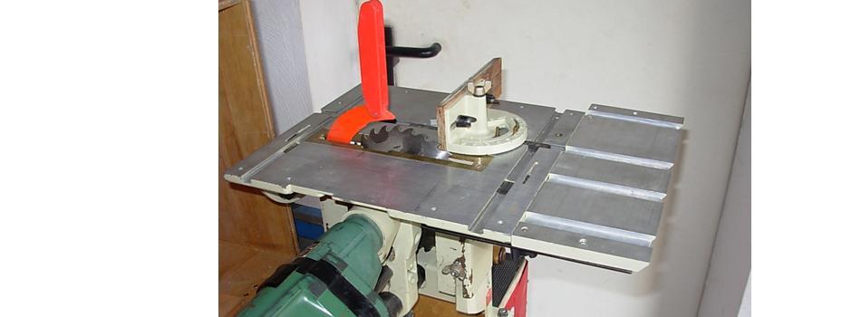
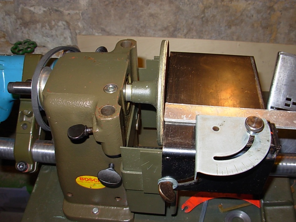
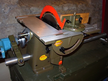 Großer Sägetisch, für Sägeblätter bis max. 150 - 160 mm. Der Tisch ist bis 45° schwenkbar.
Der Spaltkeil entspricht der ersten Version.
Um die Wanknutsägeeinrichtung zu nutzen, gab es einen zusätzlichen Verlängerungsbolzen,(siehe Ersatzteile) der den nötigen Abstand zum Spindelstock herstellte.
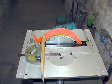
Large saw table, for saw blades up to max. 150 - 160 mm. The table can be tilted up to 45°.
The riving knife corresponds to the first version.
In order to use the roll grooving device, there was an additional extension bolt,(see spare parts) which created the necessary distance to the headstock.
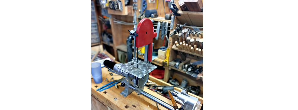
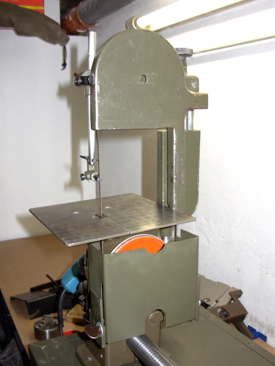
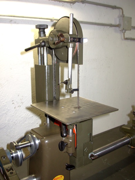
The band saw device. Band saw blade dimensions = 0.4 x 6 x 880 mm.
This accessory was already part of the very first Bosch Combi. It is only usable with the headstock.
The rear of the band saw.
If the lower running disc of the band saw was still clamped in the drill chuck of the drive machine on the first Bosch Combi, the lower disc is screwed directly onto the turning spindle here.
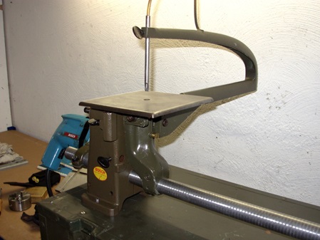
The hacksaw.
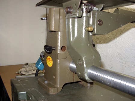
It can also be used independently of the headstock. A pipe holder and a machine holder as well as a short piece of pipe are required for this purpose.
Furthermore, a clamping shank with the mounting thread M14x1.5mm is necessary.
Fretsaw blades and also jigsaw blades can be clamped.
The upper guide tube is the hold-down and saw blade guide at the same time. A small air pump blows the dust away through this tube.
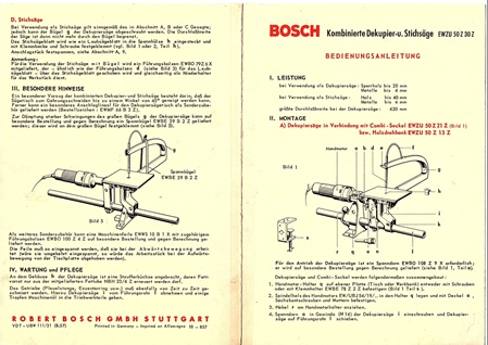
There was an extra instruction manual for the scroll and jigsaw.
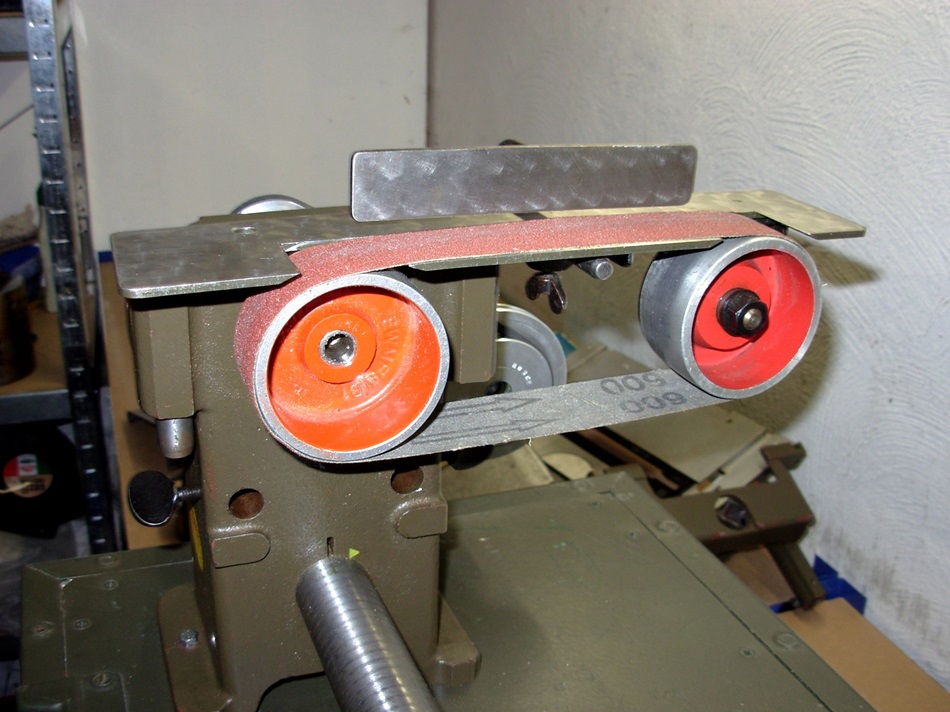
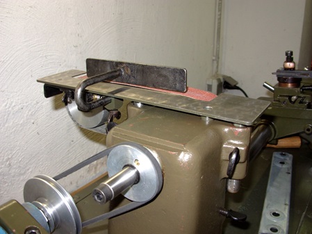
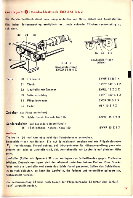
The belt grinder can only be used in conjunction with the headstock. Belt grinder dimensions 600 x 30mm.
This manual on the right also dates from 1957.
Ich habe mir aus handelsüblichen Schleifbändern, mit der entsprechenden Länge, 30mm breite Streifen abgeschnitten.
Wenn man etwas im Internet stöbert, dann findet man auch Lieferanten, die diese Bänder noch liefern können.
z.B. hier. https://www.schleiftitan.de/products/eisenblatter-schleifband-edelkorund-1?variant=46190293064
I have cut 30mm wide strips from commercial sanding belts with the corresponding length.
If you browse a bit on the internet, you can find suppliers who can still deliver these belts.
e.g. here. https://www.schleiftitan.de/products/eisenblatter-schleifband-edelkorund-1?variant=46190293064
Dressing - planing device. The small saw table is mounted turned.
Can only be used with the headstock.
Please use the protective box.
The inserted strip makes it possible to mill small tenons with a 4 mm side milling cutter.
For height adjustment, 2 different thickness shims are available. 0.5mm and 1.0mm.
The sheets are fixed at the rear end of the table in the recess for the planing roller.
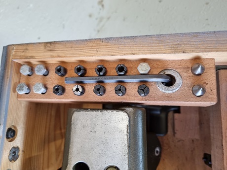
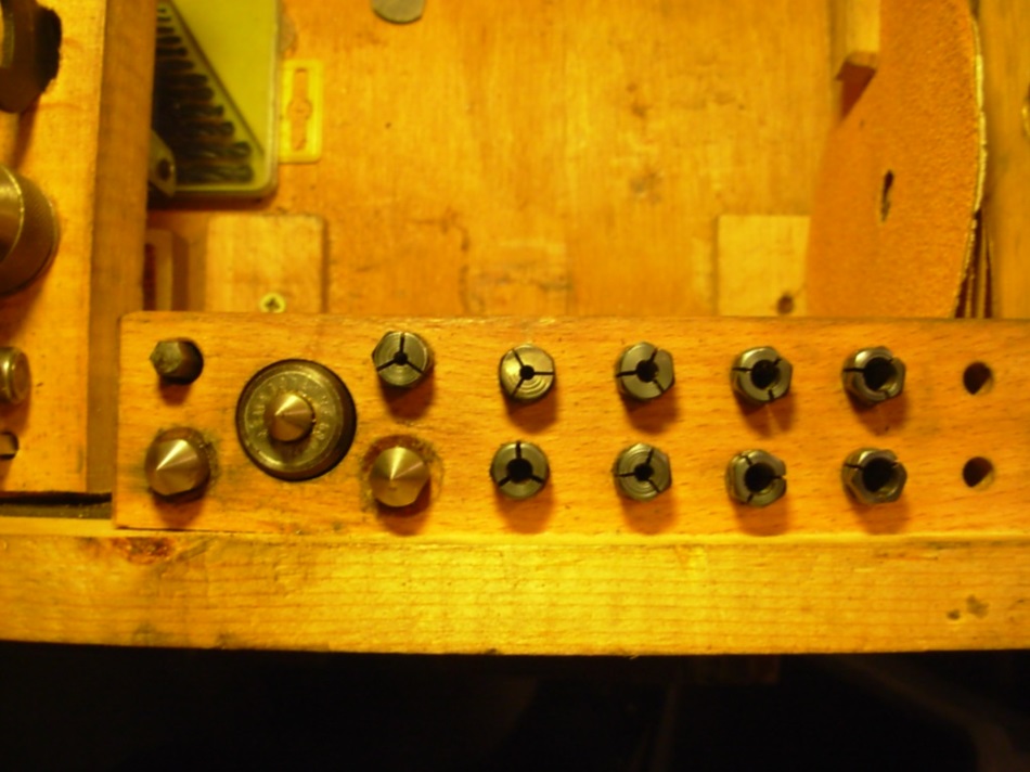
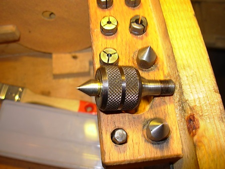
Collet in the main spindle. The collets clamp from 2mm to max. 6mm, increasing by 0.5mm each time.
Here again the self-made aluminium safety nut is screwed on.
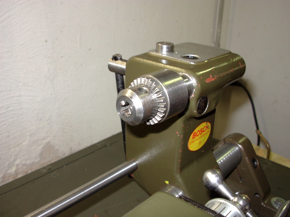 Modifiziertes Bohrfutter.
Maximalspannung 10mm. Durchspannmöglichkeit 8mm.
Dazu habe ich ein handelsübliches Bohrfutter aufgebohrt und das entsprechende Gewinde eingeschnitten und auf 8,1mm aufgebohrt.
Bei den Bohrfuttern sind nur die Spannbacken und der Verstell-Mechanismus gehärtet, der Korpus ist nicht gehärtet.
Modified drill chuck. Maximum clamping 10mm. Through clamping 8mm.
For this purpose I drilled a standard drill chuck, cut the corresponding thread and bored it to 8.1mm.
With the drill chucks only the clamping jaws and the adjusting mechanism are hardened, the body is not hardened.
Different collets from 2mm to 6mm increasing by 0.5mm.
Other accessories.
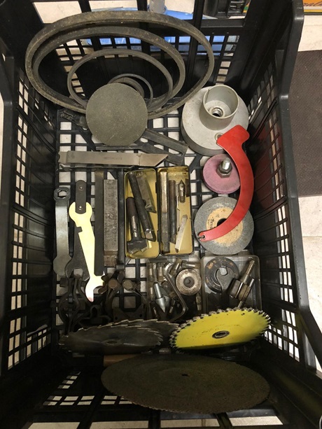
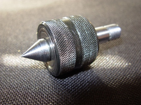
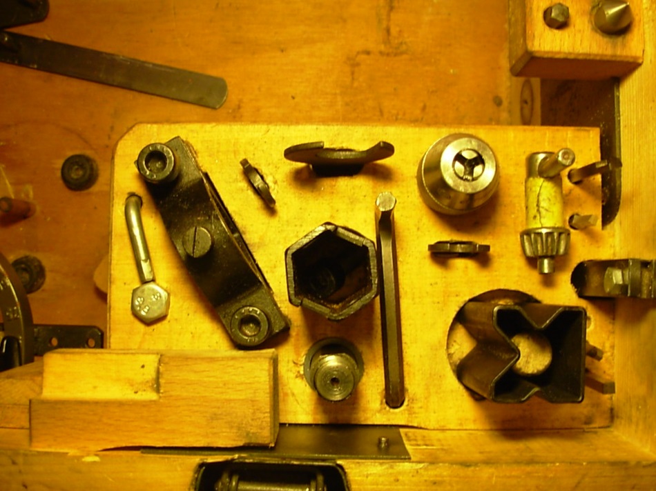
Driver for the rotating ring, various open-end spanners and pin spanners, simple drilling prism and original drill chuck.
Selbst angefertigtes Zubehör.
A drill chuck that clamps up to 10mm.
It is screwed in place of a collet chuck.
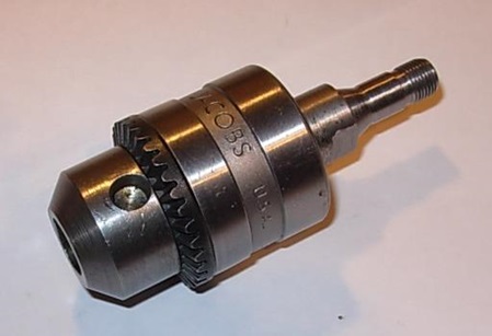
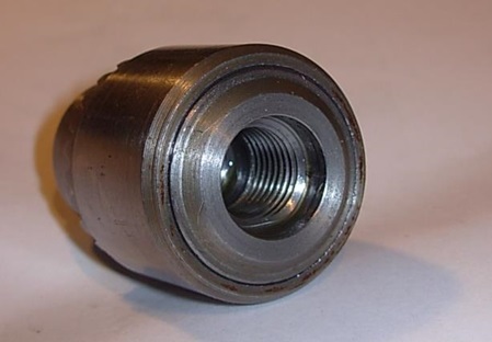 Ein weiteres Bohrfutter, welches bis 10 mm spannt.
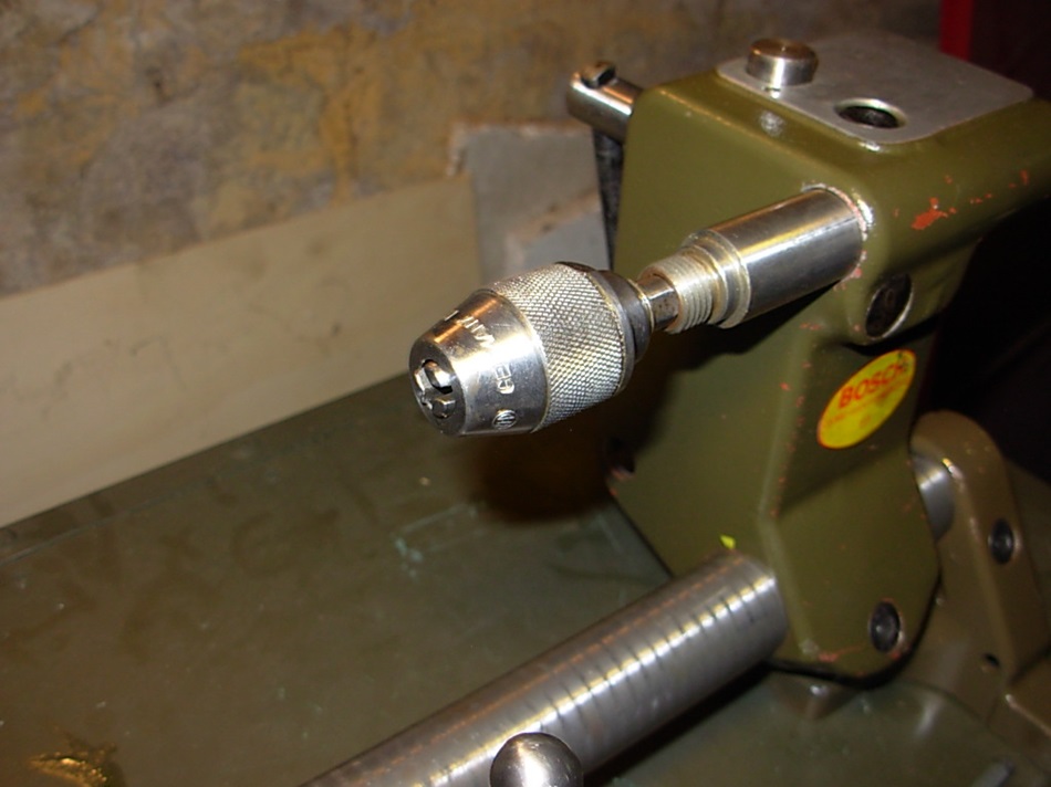
Bei diesem habe ich ein original Bohrfutter von einer Bosch Bohrmaschine verwendet. Das originale Gewinde mit UNF 1/2" x 20 Gang habe ich vergrößert und ein Gewinde mit M14 x 1,5 mm eingeschnitten. Der Passsitz hat einen Durchmesser von 16 mm. Das Bohrfutter passt sowohl auf den Spindelstock und auch auf den Reitstock der Drehmaschine.
Das Bohrfutter ist mit 8,1 mm durchbohrt, dadurch ist es möglich längere Bohrer bis 8 mm Durchmesser zu spannen.
Weiterhin hat das Bohrfutter eine Spannkapazität von max. 10 mm.
Left picture: Another drill chuck, which clamps up to 10 mm.
For this one, I used an original drill chuck from a Bosch drill. The original thread with UNF 1/2" x 20. I have enlarged and cut a thread with M14 x 1.5 mm. The fit has a diameter of 16 mm. The drill chuck fits both the headstock and the lathe tailstock.
The drill chuck is pierced with 8.1mm, so it is possible to clamp longer drills up to 8mm diameter.
Furthermore, the drill chuck has a clamping capacity of max. 10 mm.
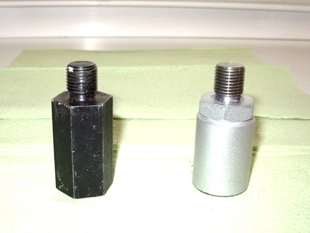
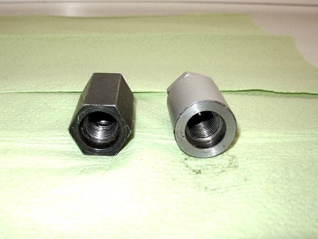
On the left the original extension bolt for the lathe and on the right the replica.
The part is needed to use the roll grooving device on the Bosch-Combi lathe.
The mounting thread in the hole is M14 x 1.5 mm.
On the other side is a thread for the clamping nut UNF 1/2" x 20.
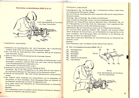
Kopiereinrichtung
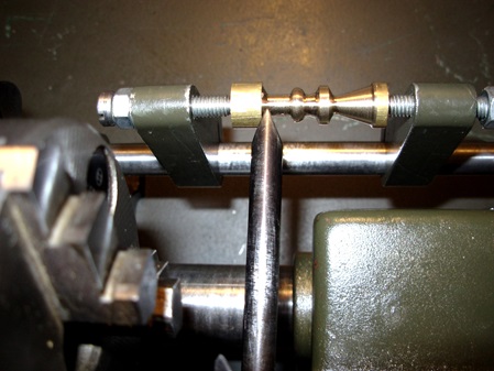
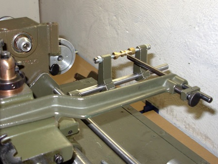
Zu der Bosch-Combi Drehmaschine gibt es auch eine Kopiereinrichtung.
Eine paralelle Führung zum Führungsrohr (Kopierträgerachse) ist die Basis.
Darauf wird dann der Kopierträger aufgespannt und als Muster dient entweder ein Originalteil oder eine Blechschablone.
Das Muster wird durch eine Abtaststift, der nachstellbar ist, abgegriffen.
Es kann immer nur eine Richtung am Kreuzsupport abgetastet werden.
Soll Längs kopiert werden, so mußte die Zustellspindel des Planschlittens ausgehängt werden.
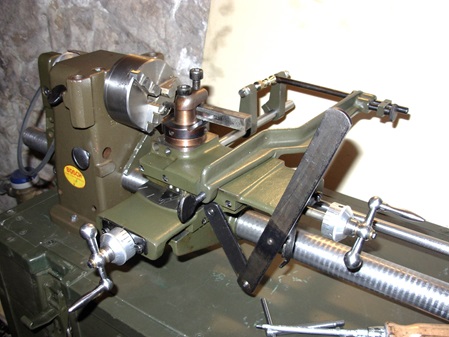
Als Zustellung dient ein Gelenkhebel, der mit Gefühl an das Muster angedrückt wird. Der Längsvorschub erfolgte über die Spindel vom Oberschlitten.
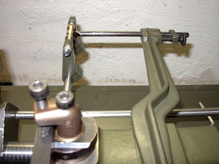
Beim Plankopieren wird ein Querträger montiert und der Abtaststift wird an einem speziellen Träger (Taststifthalter) der auf dem Oberschlitten sitzt, angesetzt.
Die Spindel vom Obersupport wird ausgehängt und der Gelenkhebel wird eingesetzt.
Die Abtastung erfolgt immer vom großen Durchmeser zum kleinen Durchmesser.
Beim Plankopieren wird immer vom höheren auf den tieferen Punkt abgetasten.
Schauen sie sich die Bilder an, dann wird das deutlich.
Copying device
There is also a copying device for the Bosch-Combi lathe.
A guide parallel to the guide tube (copy carrier axis) is the basis.
The copy carrier is then clamped onto this and either an original part or a sheet metal template serves as a sample.
The pattern is picked up by a tracing pin, which is adjustable.
Only one direction at a time can be scanned at the cross support.
If longitudinal copying is to be carried out, the feed spindle of the cross slide must be disengaged.
An articulated lever is used for feed, which is pressed against the pattern with feeling. The longitudinal feed was effected via the spindle from the top slide.
For plan copying, a cross beam is mounted and the tracing pin is attached to a special holder (tracing pin holder) which is located on the top slide.
The spindle from the top support is unhooked and the articulated lever is inserted.
The tracing is always carried out from the large diameter to the small diameter.
When copying plans, the scanning is always from the higher to the lower point.
Look at the pictures and you will see that.
Ich hatte Glück und fand, unter anderem Gerümpel, bei einem Anbieter die Einzelteile dieser Kopiereinrichtung.
Solche Teile noch zu finden, gleicht einem Lotto-Gewinn.
Die Teile waren wohl auch nicht sehr verbreitet und sind als Gebrauch-Teile nur sehr selten zu bekommen.
Ich habe die Funktion dieser Einrichtung auch erst verstanden, nach dem ich eine Bedienungsanleitung aus dem Jahre 1957 in meinen Händen hielt. In den Späteren Bedienungsanleitungen fehlt dies Anleitung leider komplett.
I was lucky and found, among other junk, the individual parts of this copying device at a supplier.
It is almost impossible to find such parts.
The parts were probably also not very common and are very rare to get as used parts.
I only understood the function of this device after holding an instruction manual from 1957 in my hands. Unfortunately, this manual is completely missing from later manuals.
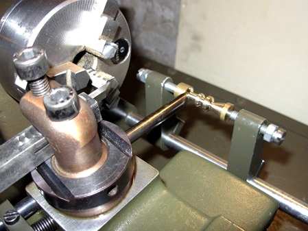
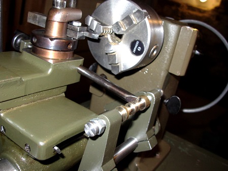
Feeler pin mounted on the top slide Copy carrier and copy pattern.
The copy carrier is mounted on the copy axis.
Unhooked facing spindle and articulated lever for scanning.
Unhooked top slide spindle and articulated lever feed.
Device for plan copying.
The additional crosshead is mounted on the copy carrier axis and the copy carrier is mounted on it. The adjustable feeler pin is mounted in the feeler pin holder, which was fixed on the upper support.
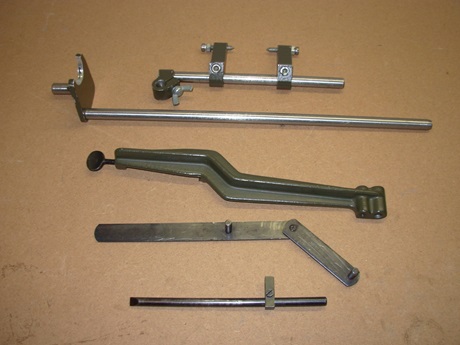
Individual parts of the copying device.
Individual parts from top to bottom with no. according to the operating instructions.
- 54-4 Cross-member with 54-2 copy carrier.
- 54-1 Copy carrier axle.
- 54-6 Feeler pin holder for plan copying.
- 54-3 Joint lever.
- 54-5 Feeler pin with clamping piece.
Hier ein Video mit der Kopiereinrichtung.
Here is a video with the copy setup.

