
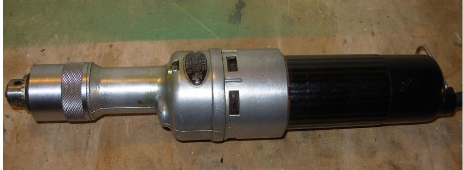
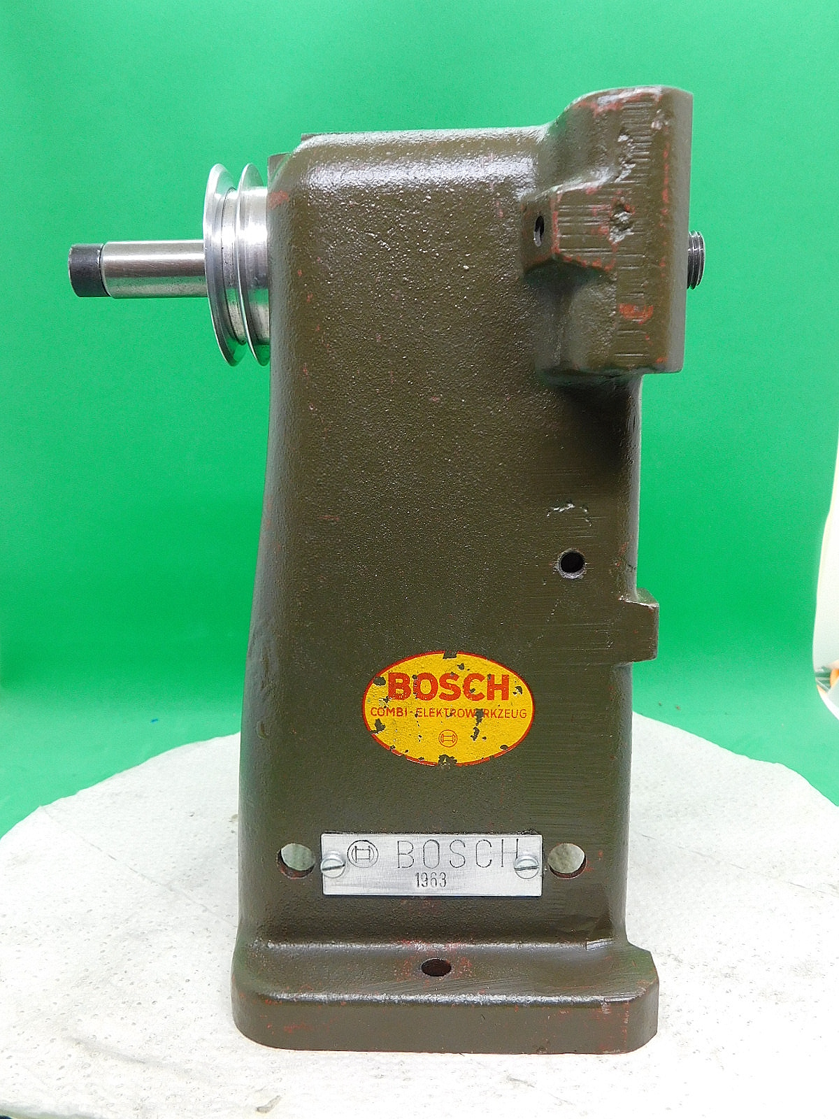
Der Spindelstock
The headstock.
Ein paar wenige Daten.
Der Spindelstock wurde aus Stahlguss, bzw. aus weißem Temperguss gefertigt.
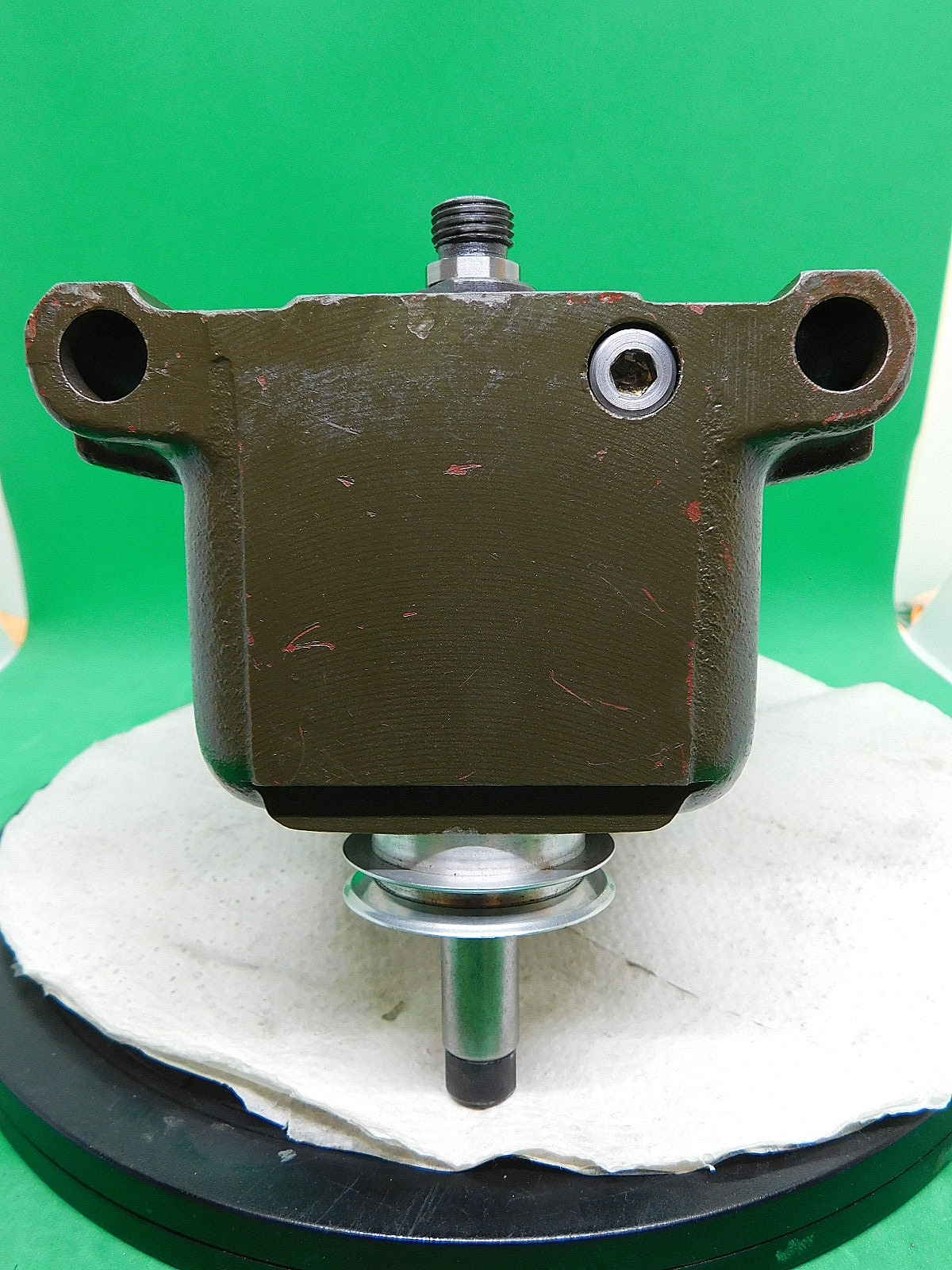
Die Spindelnase hat ein M 14 x 1,5 mm Aufnahme-Gewinde für das Drehfutter und die Planscheibe, sowie die Mitnehmer-Glocke.
Der Passsitz hat einen Durchmesser von 16 mm.
Innen hat sie ein M 8 x 0,75 mm Aufnahme-Gewinde und einen Passsitz für die 8 mm Spannzangen und die Drehspitze.
Die Spindel ist nicht durchbohrt.
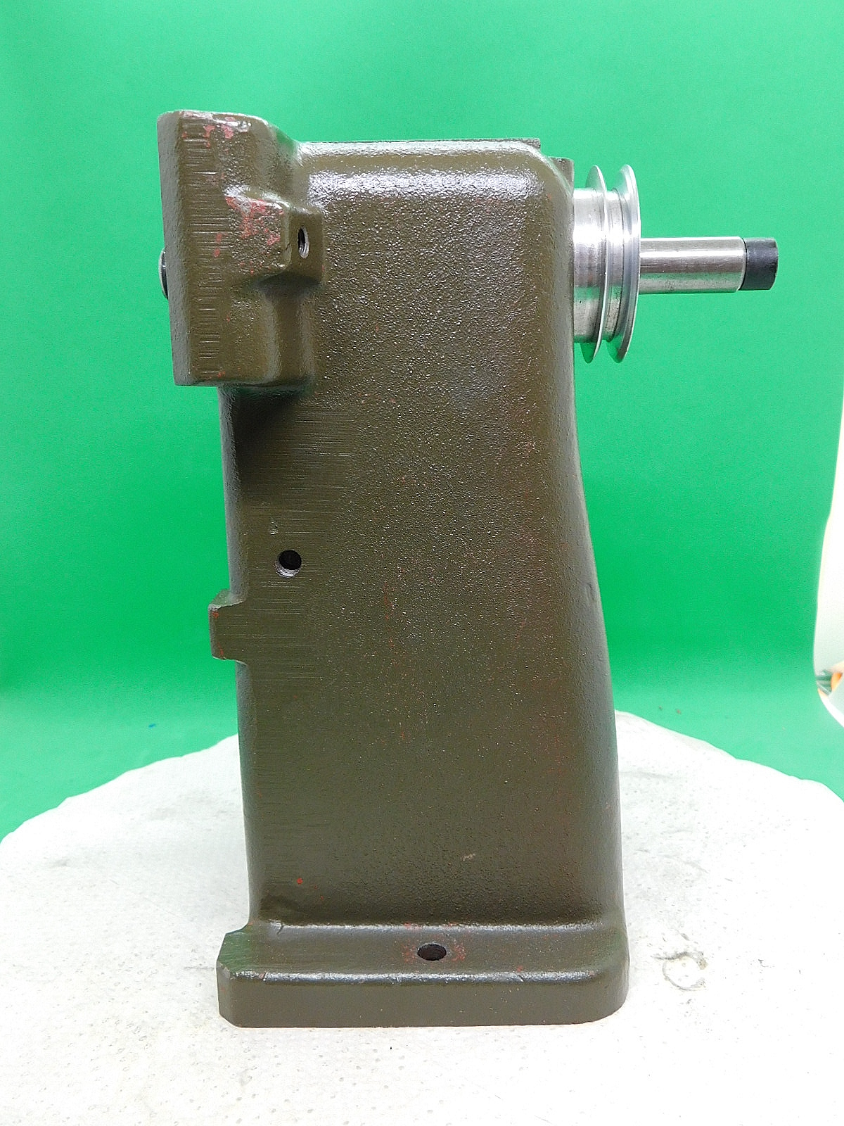
Am hinteren Ende, mit einem Durchmesser von 14 mm, sitzt die Riemenscheibe auf der Spindel . Eine zusätzliche Stufenscheibe, die gleichzeitig die Aufnahme für eine Schleifscheibe bildet, kann man auf dieses Ende aufschieben und mit der Innensechskantschraube sichern. Diese zusätzliche Antrieb-Scheibe wird über einen Passstift, der in die fest verbaute Antriebscheibe eingreift mit genommen.
A few details.
The headstock was made of cast steel or white tempered cast iron.
The spindle nose has an M 14 x 1.5 mm mounting thread for the lathe chuck and the faceplate, as well as the driver bell.
The fit has a diameter of 16 mm.
On the inside, it has an M 8 x 0.75 mm mounting thread and a fit for the 8 mm collets and the turning center.
The spindle is not drilled through.
At the rear end, with a diameter of 14 mm, the pulley sits on the spindle. An additional stepped pulley, which also forms the holder for a grinding wheel, can be slid onto this end and secured with the hexagon socket screw. This additional drive disk is taken along via a dowel pin that engages in the permanently installed drive disk.
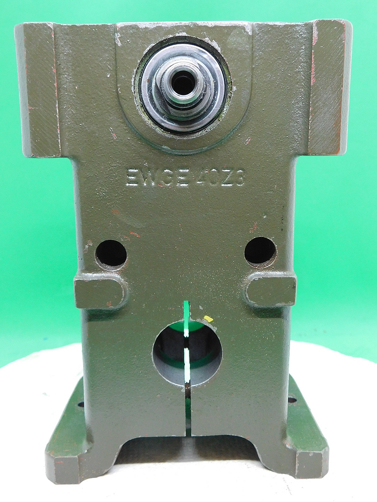
Im Spindelstock befinden sich einige Aufnahmebohrunge und Gewinde. In der Mitte ist die Bohrung für das Zentrale Verbindungsrohr. Dieses wird mit zwei M 8 Schrauben geklemmt.
Weitere Bohrungen mit einem Durchmesser von 13 mm, die zur Aufnahme von Zusatzgeräten dienen, befinden sich an der Ober- und Frontseite. Die Letzte Ausführung des Spindelstockes, ab ca. 1968 hatte diese Bohrungen allerdings nicht mehr.
There are several locating holes and threads in the headstock. The hole for the central connecting tube is in the center. This is clamped with two M 8 screws.
Further holes with a diameter of 13 mm are located on the top and front of the headstock to accommodate additional equipment. However, the last version of the headstock, from around 1968, no longer had these holes.
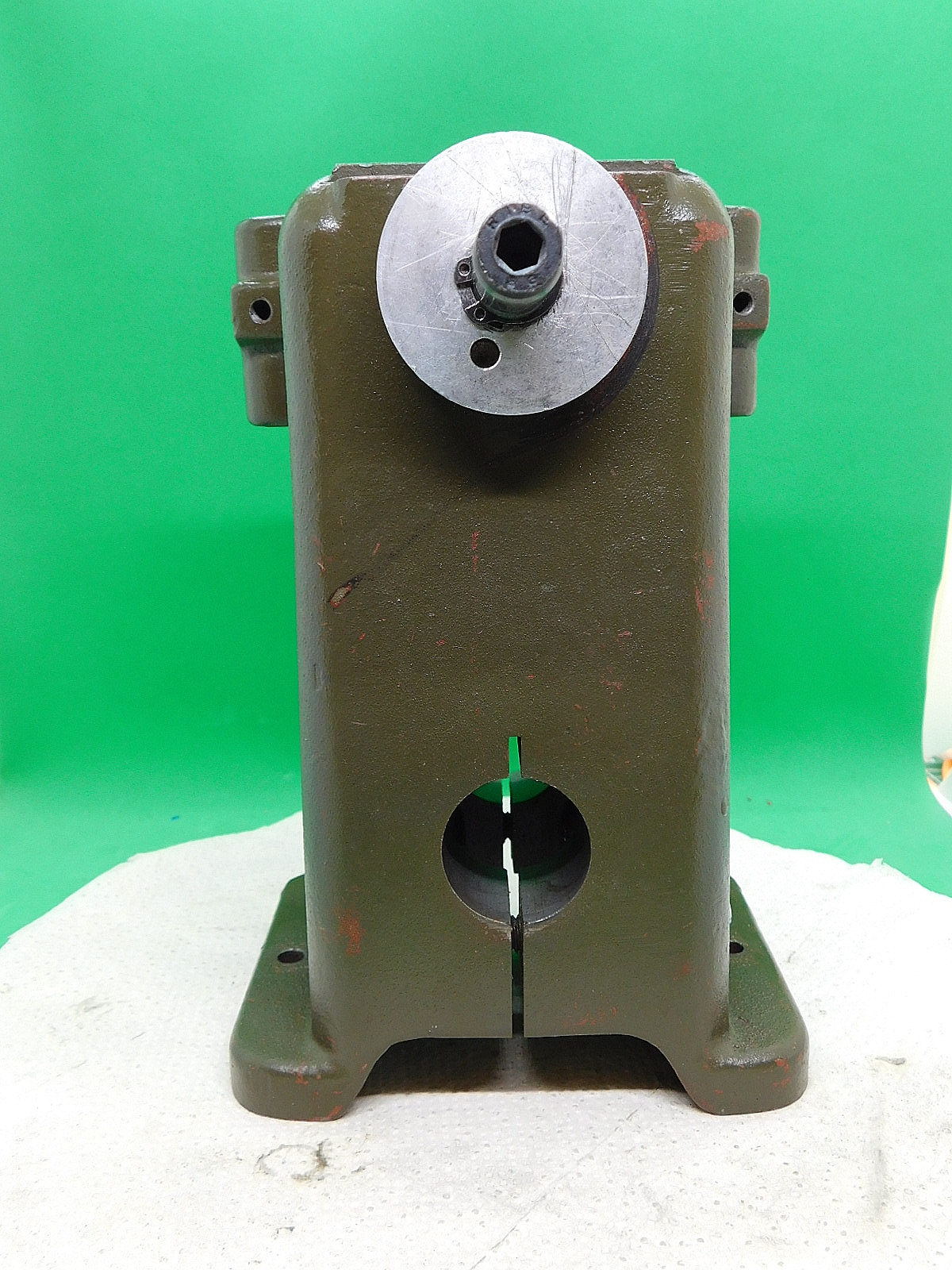
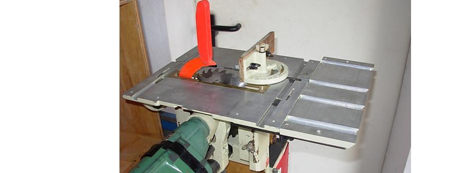
Die M8 Innensechskantschraube auf der Oberseite vom Spindelstock ist für die Höheneinstellung des kleinen Sägetisches und vom Bandschleifer. der 2. Generation.
The M8 hexagon socket screw on the top of the headstock is for adjusting the height of the small saw table and the 2nd generation belt sander.
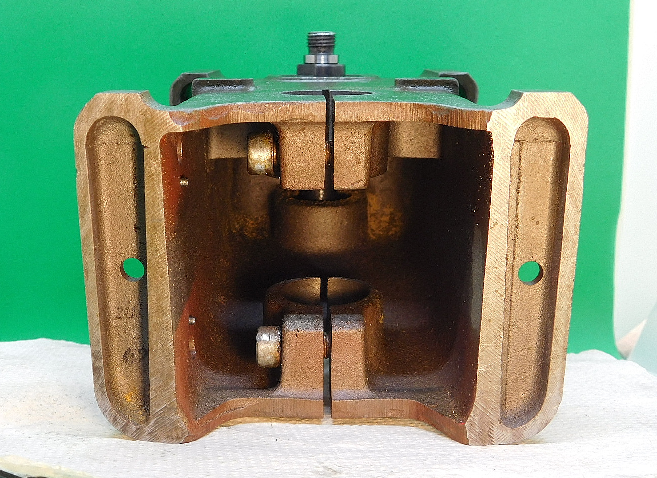
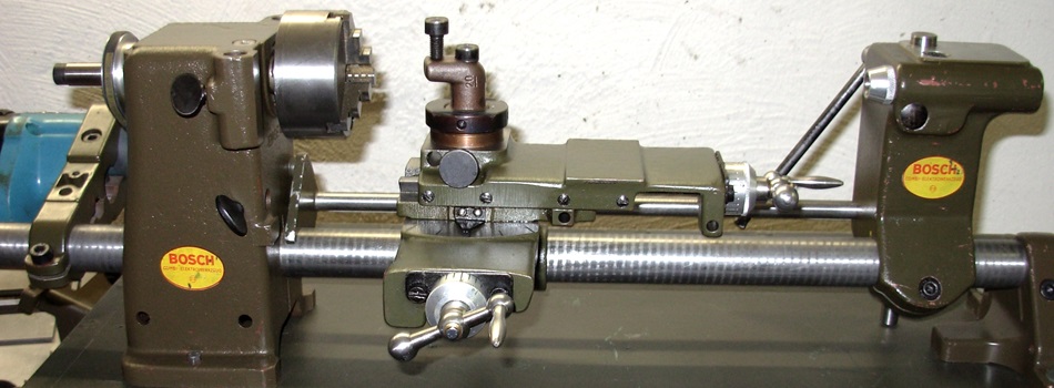
Der Spindelstock ist sehr massiv ausgeführt.
Mit zwei M8 Schrauben wird das zentrale Verbindungsrohr geklemmt.
The headstock has a very solid design.
The central connecting tube is clamped with two M8 screws.
Spindelstock / Spindel Wartung.
In den alten Bedienungsanleitungen gibt es eine Wartung- und Pflege- Anweisung. Danach sollen die Spindel-Lager dauer schmierend sein.
Bei so alten Maschinen, sollte man allerdings auch mal ein Auge auf die Spindel-Lager werfen, reinigen und neu schmieren.
Als Schmierstoff verwende ich gutes Kugellager-Fett.
z.B. "Autol Top 2000"
Es gibt immer mal wieder Unklarheiten, wie die Lageranordnung und vor Allem die unterschiedlichen Scheiben der Hauptspindel eingesetzt werden.
An der Futterseite ist ein normales Kugellager ohne Kapselung verbaut. Den Abschluss nach außen bildet eine geprägte, dünne Blechscheibe.
Typ 6003 oder 6003-2Z ; Maße 17 x 35 x 10mm.
Bitte keine voll gekapselte Lager mit Kunststoffabdeckungen einbauen, Diese Lager haben zu viel Eigenreibung.
An der Antrieb-Seite ist ein Schulterkugellager E15 / EN15 15x35x8 mm verbaut. Solche Lager sind sehr schwer und wenn, dann relativ teuer zu bekommen.
Eine Bezugsquelle ist z.B. Hier--->>https://www.kugellager-express.de/schulterkugellager__35_2__8__15
Eine Alternative sind Schrägkugellager vom Typ 7202-B ISB; Maße 15 x 35 x 11mm.
Sollte man so ein Schrägkugellager verwenden, dann muss die Zentrierscheibe der Blattfeder und evtl. Die Antriebscheibe modifiziert werden. Das muss man vor Ort anpassen.
Das Schrägkugellager hat eine Breite von 11mm und baut 3 mm breiter als das originale Schulter-Lager.
Headstock / Spindle service.
There are maintenance and care instructions in the old operating instructions. According to these, the spindle bearings should be permanently lubricated.
With such old machines, however, you should also keep an eye on the spindle bearings, clean and relubricate them.
I use good ball bearing grease as a lubricant.
e.g. "Autol Top 2000"
There is always some confusion as to how the bearings are arranged and, above all, how the different discs of the main spindle are used.
A normal ball bearing without encapsulation is installed on the chuck side. An embossed, thin sheet metal disk forms the outer end.
Type 6003 or 6003-2Z; dimensions 17 x 35 x 10mm.
Please do not install fully enclosed bearings with plastic covers, these bearings have too much inherent friction.
An E15 / EN15 15x35x8 mm shoulder ball bearing is installed on the drive side. Such bearings are very difficult to obtain and, if so, relatively expensive.
A source of supply is e.g. here--->> https://www.kugellager-express.de/schulterkugellager__35_2__8__15
An alternative are angular contact ball bearings of the type 7202-B ISB; dimensions 15 x 35 x 11mm.
If you use such an angular contact ball bearing, the centring disc of the leaf spring and possibly the drive disc must be modified. This has to be adjusted on site.
The angular contact ball bearing has a width of 11 mm and is 3 mm wider than the original shoulder bearing.
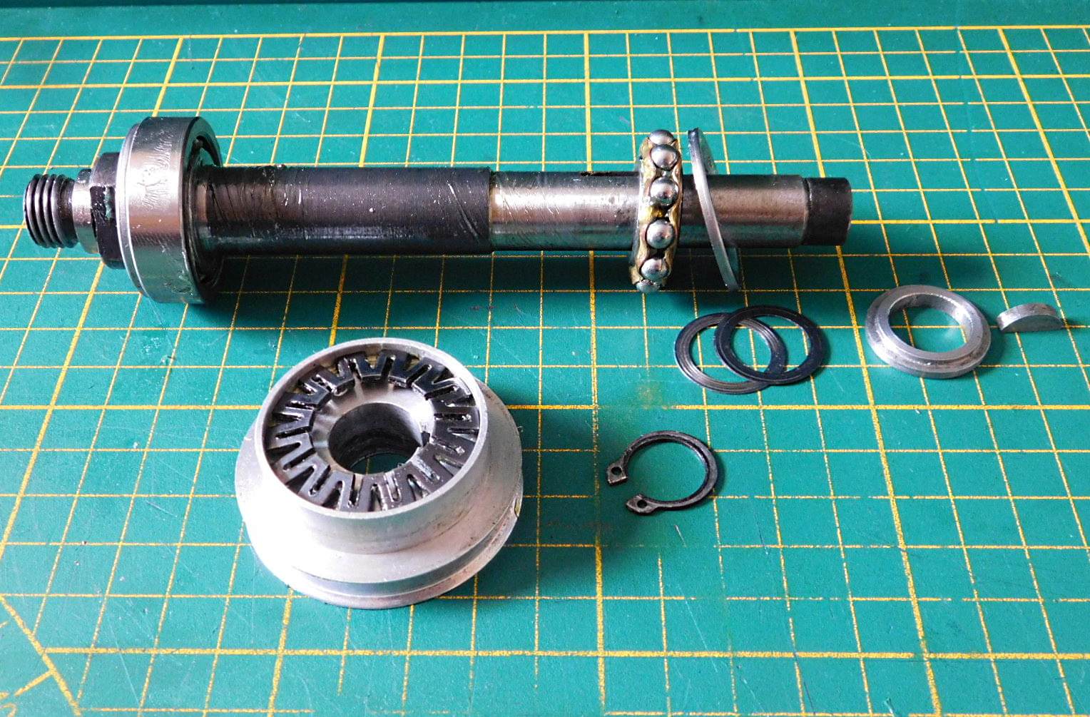 Die Spindel der Drehmaschine mit ihren Lagern Scheiben und Federteller, sowie Antriebscheibe.
The spindle of the lathe with its bearings, discs and spring plates, as well as the drive disc.
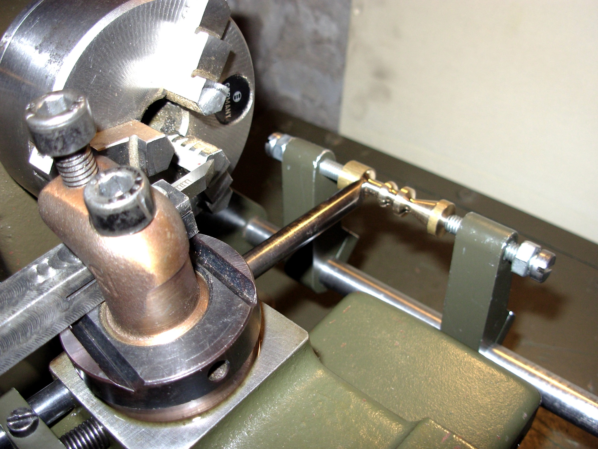
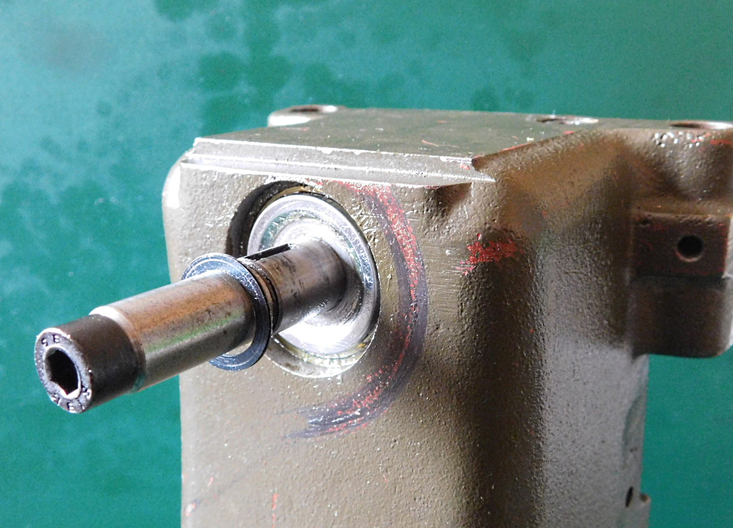
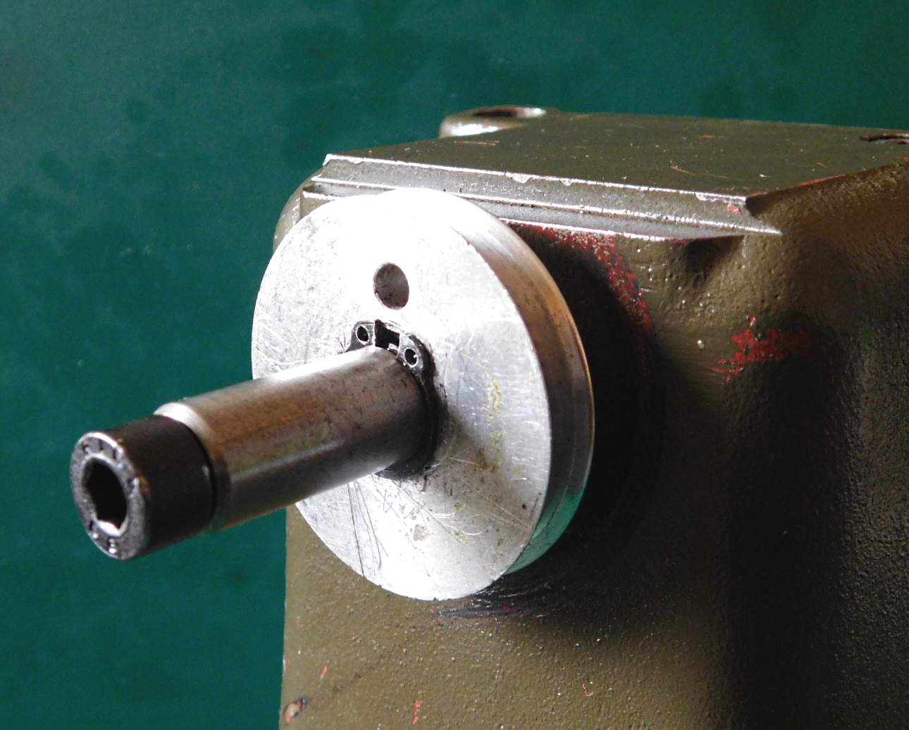
 Spindel im Spindelstock eingesetzt. Das hintere Lager ist aufgeschoben.
Spindle inserted in headstock. The rear bearing is pushed on.
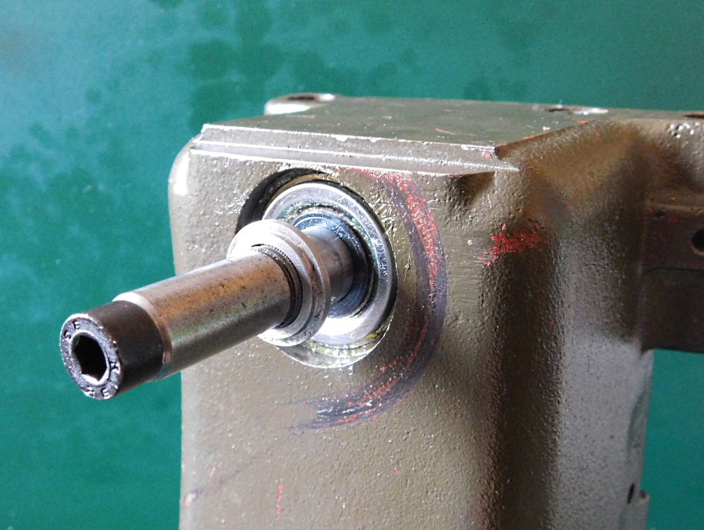
 Lagerabdeckscheibe einsetzen.
Insert the bearing cover washer.
Passscheiben aufschieben.
Diese Passscheiben gibt es in unterschiedlichen Dicken.
Slide on the shims.
These shims are available in different thicknesses.
 Druckscheibe mit Zentrierbund für die Feder der Lagervorspannung aufschieben.
Slide on the thrust washer with centring collar for the bearing preload spring.
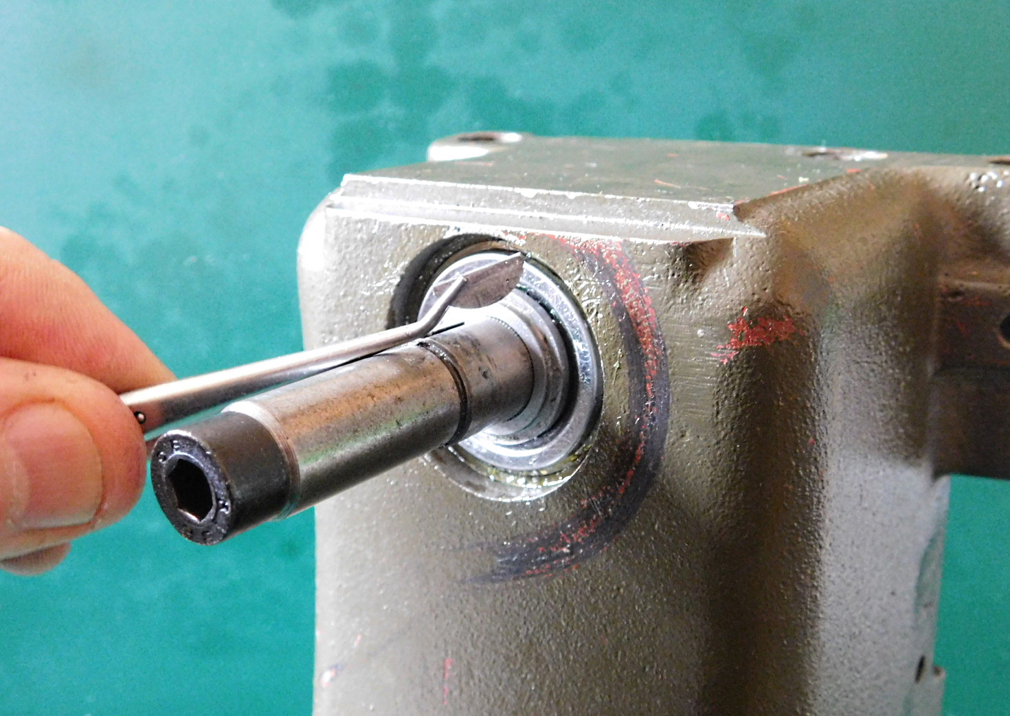 Scheibenfeder einsetzen.
Insert the Woodruff key.
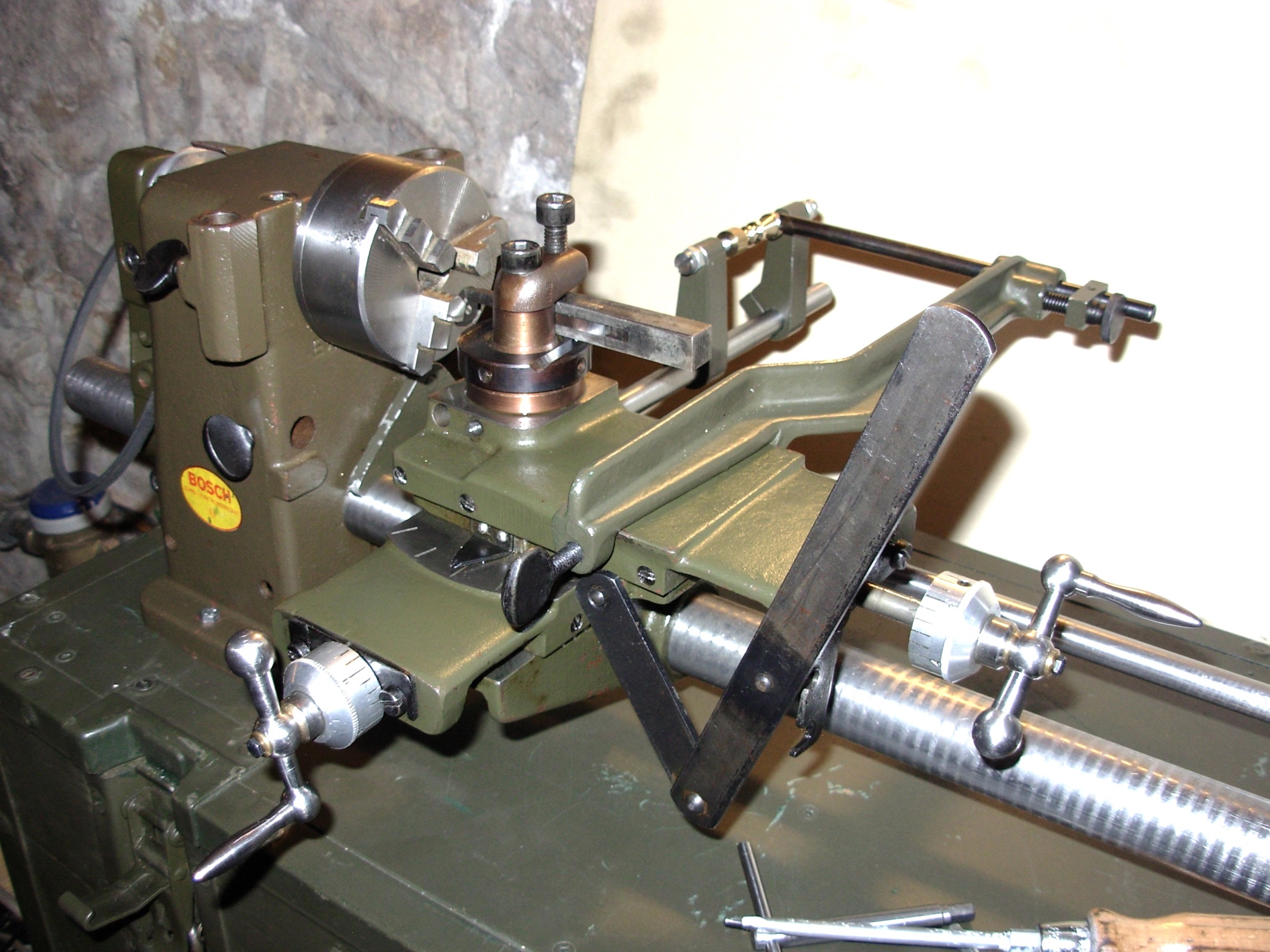
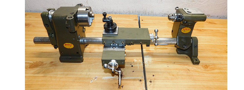
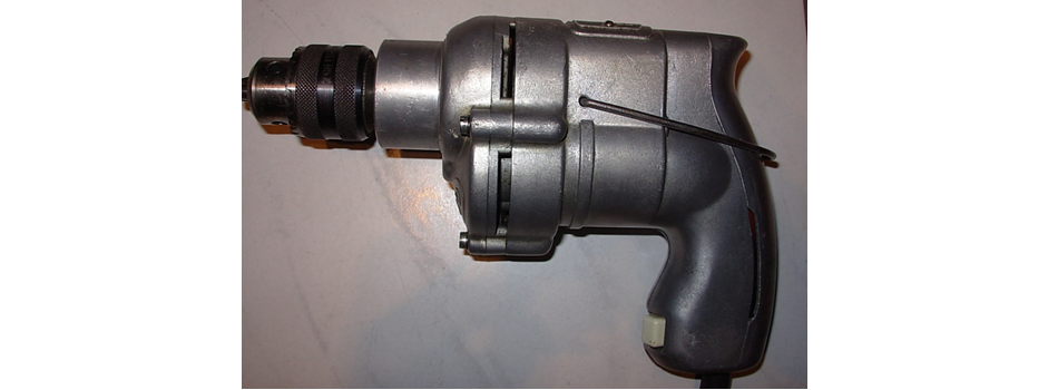
 Beide Vorspannfedern einsetzen.
Bei der Montage ist es manchmal besser die Tellerfedern in die Antriebscheibe zu legen und die Teile so einzubauen. All zu leicht rutschen die Tellerfedern von der Zentrierscheibe und verklemmen sich bei der Montage.
Zu sehen auf dem ersten Bild bei diesem Artikel.
Insert the two preload springs.
When assembling, it is sometimes better to place the disc springs in the drive disc and install the parts that way. It is all too easy for the disc springs to slip off the centring disc and get jammed during assembly.
You can see it in the first picture of this article.
 Antriebscheibe auf die Scheibenfeder auffädeln, die Scheibenfedern etwas zusammen drücken und mit dem Wellen-Sicherungsring befestigen. Die scharfe Kante des Sicherungsringes muss dabei nach außen zeigen, sonst besteht die Gefahr, dass er abrutscht.
Thread the drive washer onto the Woodruff key, press the Woodruff keys together slightly and secure with the circlip. The sharp edge of the retaining ring must point outwards, otherwise there is a risk of it slipping off.
Die Demontage geschieht natürlich in umgekehrter Reihenfolge.
Disassembly is of course done in reverse order.
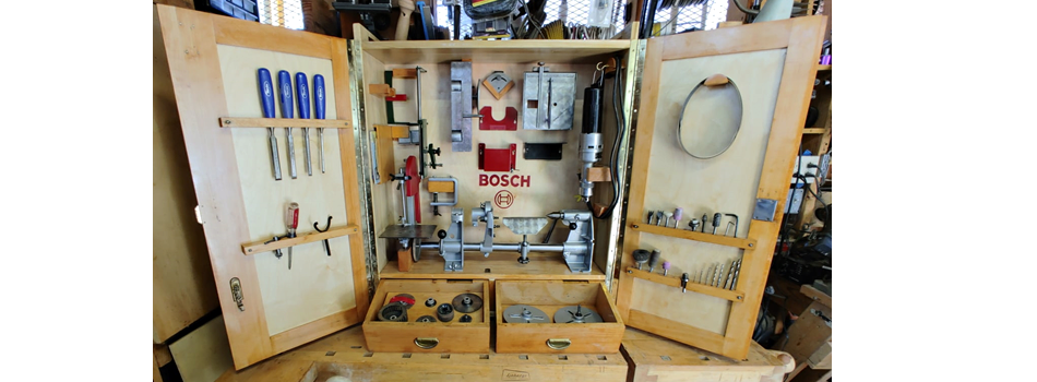
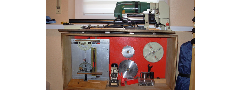
Anbaugeräte für den Spindelstock.
Attachments for the headstock.
Für den Spindelstock wurden einige Anbaugeräte entwickelt. Teilweise waren diese schon bei der ersten Ausführung vom Bosch-Combi-Gerät vorhanden.
Ohne den Spindelstoch können diese Geräte nich in Betrieb genommen werden.
A few attachments were built for the headstock. Some of these were already available on the first version of the Bosch combi tool.
These devices cannot be put into operation without the headstock.
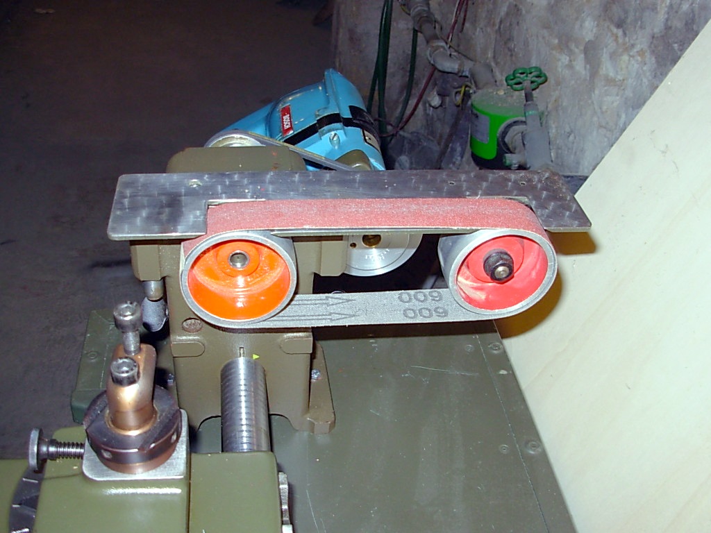
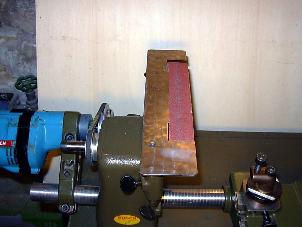
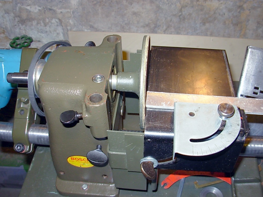
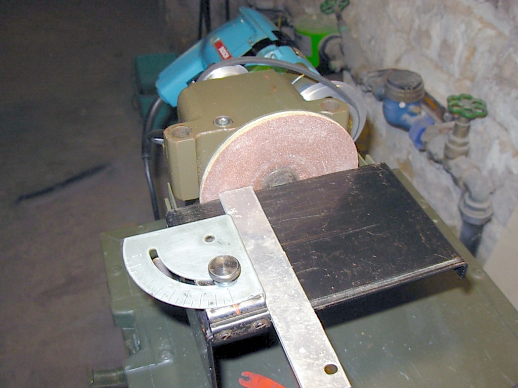
Bandschleifer, Belt grinder.
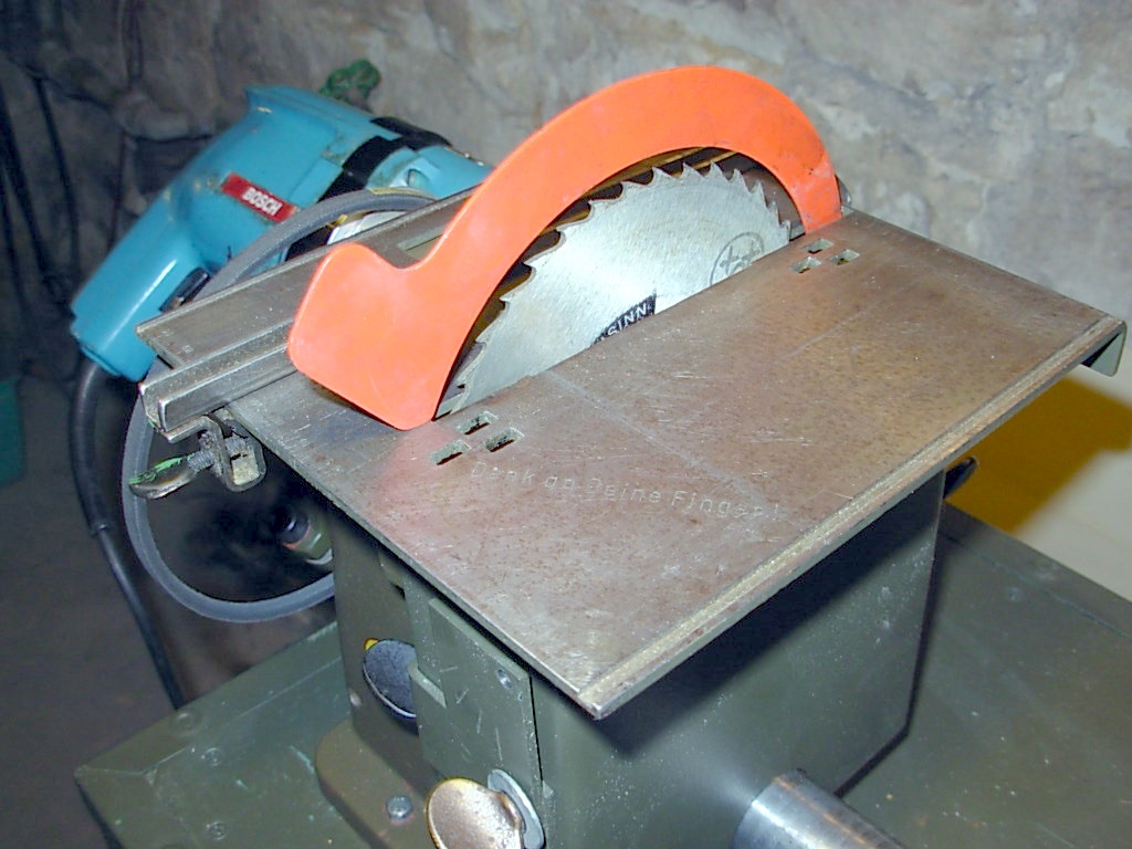
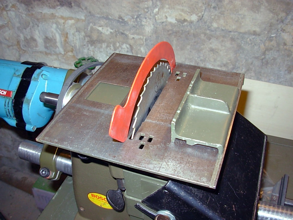
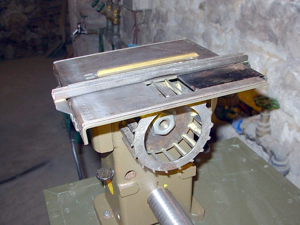
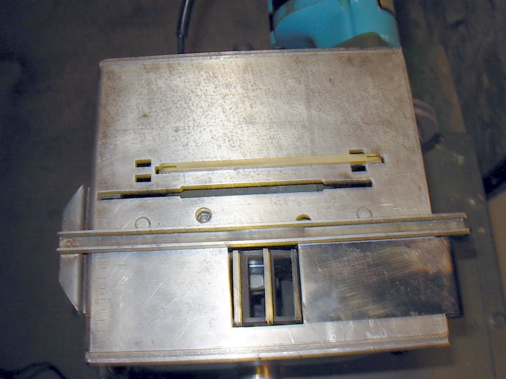
Kleiner Sägetisch, Small saw table.
Hobel-Einrichtung, Planing device.
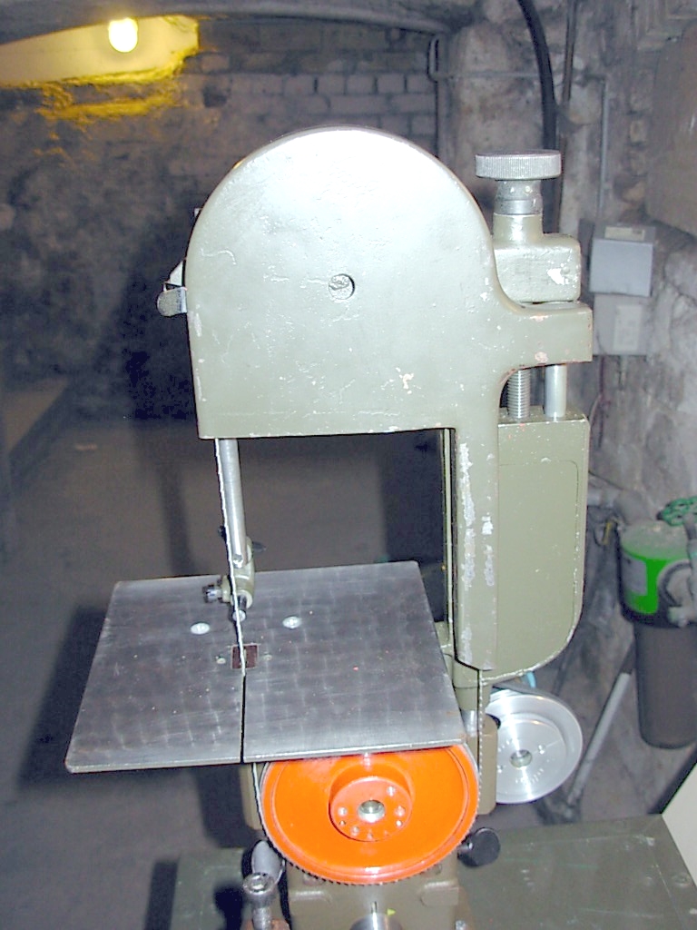
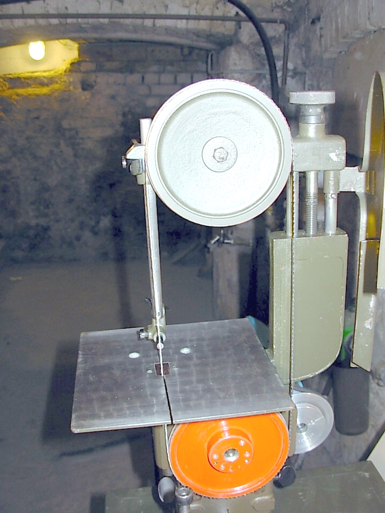
Bandsäge Einrichtung, Bandsaw equipment.
Dieses Gerät war schon Bestandteil des ertsen Bosch Combi-Gerätes.
This attachment was already part of the first Bosch Combi machine.
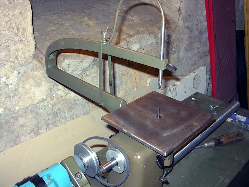
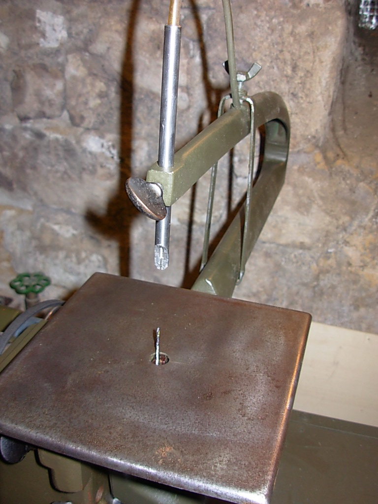
Decupier -und Stichsäge, Decupier and jigsaw
Schleifteller mit Schleiftisch, Sanding disc with sanding table.
Kopiereinrichtung der Drehmaschine, Copying device for the lathe.